Industrial oil/dust collector

a technology of oil/dust collectors and oil sucking, which is applied in the direction of vehicle cleaning, cleaning filter means, separation processes, etc., can solve the problems of increasing the cost of buying a new oil/dust collector, easy damage to the motor, and time-consuming and labor-intensive problems of cleaning, so as to prolong the service life of the motor, save time and money, and save costs

Inactive Publication Date: 2006-09-19
CHO KUO CHIN
View PDF6 Cites 10 Cited by
  • Summary
  • Abstract
  • Description
  • Claims
  • Application Information

AI Technical Summary

Benefits of technology

The technical effect of this patent is to create an improved industrial oil/dust collector that solves issues associated with existing systems by effectively removing oily substances and keeping equipment running clean for longer periods of time. Additionally, it provides more efficient and effective filtration capabilities through its use of multiple stages and easy replacement of filters. Furthermore, the system includes a spare oil-collecting tank designed to improve safety and prevent damage caused by overloaded motors and other machinery.

Problems solved by technology

The technical problem addressed in this patent is that current industrial oil/dust collectors have limitations such as slow emptying times, incomplete closure of liquids during collection, and difficulty removing metal impurities. This results in increased costs and potential damage to machinery.

Method used


Image

  • Industrial oil/dust collector
  • Industrial oil/dust collector
  • Industrial oil/dust collector

Examples


Embodiment Construction

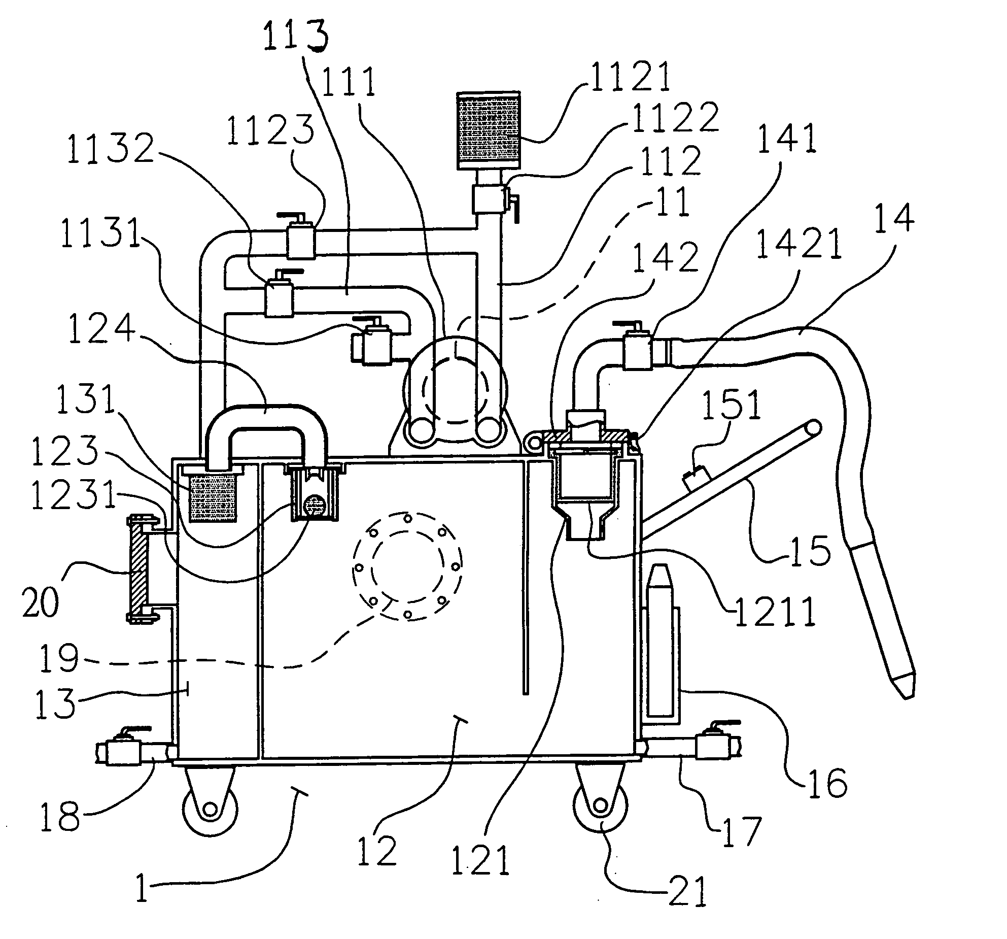
[0027]Referring to FIG. 3, an industrial oil / dust collector includes a base 1, and an oil-collecting tank 12 and a spare oil-collecting tank 13 are provided in the interior of the base 1. A motor 11 is installed on the exterior of the base 1, an air blower 111 is provided at the back of the motor 11, and an air-inlet pipe 112 and an air-outlet pipe 113 are provided at the front of the motor 11. An air filter 1121 is provided on the upper end of the air-inlet pipe 112, a first switch valve 1122 and a second switch valve 1123 are provided at the bottom of the air filter 1121, and the bottom end of the air-inlet pipe 112 is connected to the spare oil-collecting tank 13. The air-outlet pipe 113 is provided with a third switch valve 1131 and a fourth switch valve 1132, and the bottom end of the air-outlet pipe 113 is connected to the spare oil-collecting tank 13.

[0028]The oil-collecting tank 12 is pivotally jointed with a suction pipe 14, which is provided with a switch valve 141. One en...


PUM


Abstract

An industrial oil/dust collector is provided with a base, a motor and an air blower are installed on the exterior of the base, an air-inlet pipe and an air-outlet pipe are provided at the front of the motor to carry out quick suction and drainage functions, and inside the base there are an oil-collecting tank and a spare oil-collecting tank provided with multiple filtering devices to filter impurities of the oil, so as to prolong the service life of the motor and the air blower.

Description


Claims


Application Information

Patent Timeline
Owner CHO KUO CHIN
Why Eureka
Try Eureka