Webbing retractor

a retractor and webbing technology, applied in the field of webbing retractors, can solve the problems of excessively rapid taking up and the like of webbing belts

Active Publication Date: 2006-09-19
KK TOKAI RIKA DENKI SEISAKUSHO
View PDF23 Cites 17 Cited by
  • Summary
  • Abstract
  • Description
  • Claims
  • Application Information

AI Technical Summary

Benefits of technology

[0016]In view of the aforementioned, an object of the present invention is to provide a webbing retractor which generates relative rotation between a prime mover rotating body and a rotating body such as an inertial plate or the like so as to reliably transmit rotation of the prime mover rotating body to a driven shaft, such that taking-up of a webbing belt by the driving force of a driving mechanism can be carried out.

Problems solved by technology

Thus, the taking-up and the like of the webbing belt are carried out excessively rapidly.

Method used


Image

  • Webbing retractor
  • Webbing retractor
  • Webbing retractor

Examples


first embodiment

STRUCTURE OF FIRST EMBODIMENT

(Overall Structure of Webbing Retractor 10)

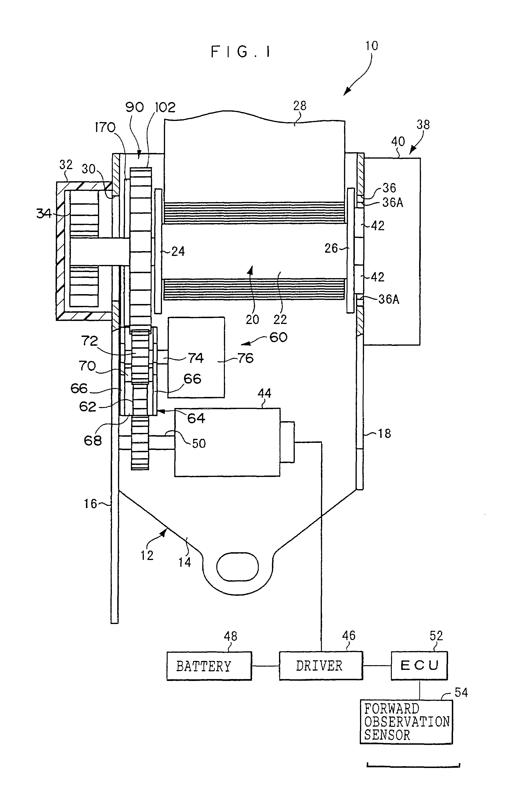
[0076]A front sectional view showing the overall structure of a webbing retractor 10 relating to a first embodiment of the present invention is shown in FIG. 1. As shown in FIG. 1, the webbing retractor 10 has a frame 12. The frame 12 has a back plate 14 which is substantially plate-shaped. The webbing retractor 10 is mounted to a vehicle body by the back plate 14 being fixed to the vehicle body by unillustrated fasteners such as bolts or the like. A pair of leg plates 16, 18 extend parallel to one another from the transverse direction ends of the back plate 14. A spool 20, which serves as a take-up shaft and is manufactured by die casting or the like, is disposed rotatably between the leg plates 16, 18.

[0077]The spool 20 is structured by a spool main body 22 and a pair of flange portions 24, 26, and is formed in a drum-shape on the whole. The spool main body 22 is substantially hollow cylindrical. The pair of f...

second embodiment

OPERATION AND EFFECTS OF SECOND EMBODIMENT

[0177]Next, the operation and effects of the present embodiment will be described by way of explaining the operation of the present webbing retractor 290.

(Operation of Webbing Retractor 290 when Approaching an Obstacle Ahead)

[0178]In the present embodiment, when the vehicle is traveling, the forward observation sensor 54 detects the distance to an obstacle ahead of the vehicle. An electric signal, which has a signal level corresponding to the distance to the obstacle, is outputted from the forward observation sensor 54.

[0179]The electric signal outputted from the forward observation sensor 54 is inputted to the ECU 52. At the ECU 52, on the basis of the electric signal from the forward observation sensor 54, it is judged whether or not the distance to the obstacle is less than a predetermined value.

[0180]Next, when it is judged at the ECU 52 that the distance to the obstacle is less than a predetermined value, the ECU 52 outputs a control si...

third embodiment

STRUCTURE OF THIRD EMBODIMENT

[0208]Next, a third embodiment of the present invention will be described.

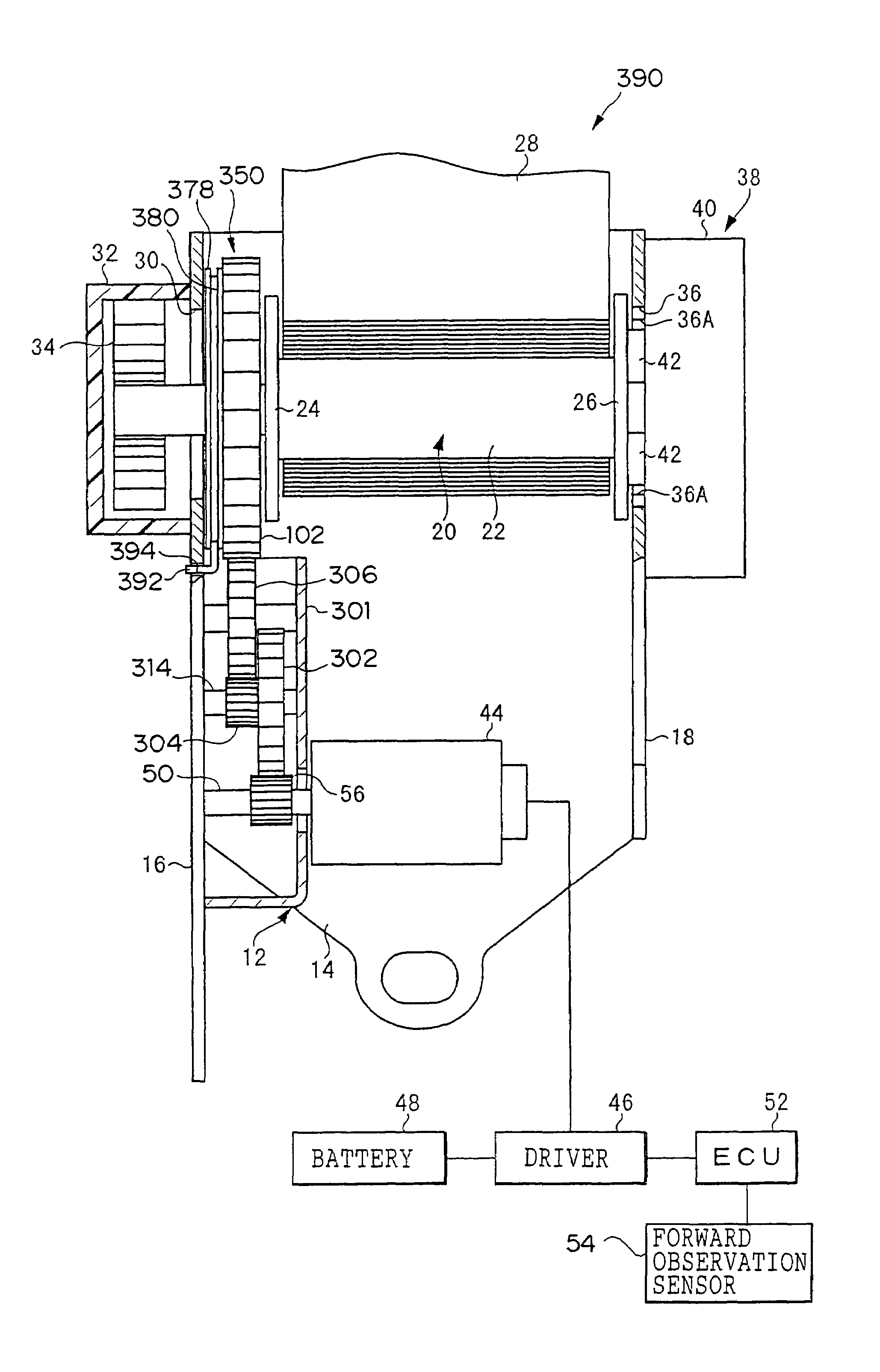
[0209]The basics of the structure of a webbing retractor 390 relating to the present embodiment are shown in front view in FIG. 14. The basics of the structure of the webbing retractor 390 are shown in exploded perspective view in FIG. 15. As shown in these figures, in the same way as the webbing retractor 290 relating to the above-described second embodiment, the webbing retractor 390 has the gears 302, 304, 306.

[0210]However, the present webbing retractor 390 does not have the arm 308 and the lever 320. Accordingly, in the present embodiment, the gears 302, 304, 306 do not structure the braking mechanism, and are merely a reduction gear train for decelerating the rotation of the output shaft 50 of the motor 44 and transmitting it to the external gear 102.

[0211]In this way, the present webbing retractor 390 differs from the webbing retractor 290 relating to the second embodiment i...


PUM


Abstract

A webbing retractor which, by causing relative rotation between a prime mover rotating body and a rotating disc, connects the prime mover rotating body and a driven shaft which is connected to a take-up shaft of a webbing belt. A planet gear is pivotally supported at a plate having a braking piece and meshes with a sun gear. The plate is supported so as to be swingable around the sun gear. When the sun gear is driven to rotate at greater than a predetermined speed, the planet gear begins to circle around the sun gear against urging force of a spring attached to the plate, and makes the plate rotate such that the braking piece slidingly contacts the friction ring. Due to this braking, the rotating disc connected to the friction ring rotates relative to the prime mover rotating body.

Description

CROSS-REFERENCE TO RELATED APPLICATION[0001]This application claims priority under 35 USC 119 from Japanese patent Application No. 2002-202970, the disclosure of which is incorporated by reference herein.BACKGROUND OF THE INVENTION[0002]1. Field of the Invention[0003]The present invention relates to a webbing retractor which structures a seat belt device for restraining, by an elongated, strip-shaped webbing belt, the body of a vehicle occupant who is seated in a seat of a vehicle or the like.[0004]2. Description of the Related Art[0005]A seat belt device which restrains, by an elongated, strip-shaped webbing belt, the body of a vehicle occupant who is seated in a seat of a vehicle, is equipped with a webbing retractor which is fixed to the vehicle body at the side of the seat. The webbing retractor has a spool (take-up shaft) whose axial direction runs, for example, substantially along the longitudinal direction of the vehicle. The proximal end side, in the longitudinal direction, ...

Claims


Application Information

Patent Timeline
Patent Type & Authority Patents(United States)
IPC IPC(8): B60R22/46B60R22/48
CPCB60R22/46B60R2022/468B60R2022/4666
Inventor MORI, SHINJIKOMIYA, FUMINORIKOIDE, TERUHIKO
Owner KK TOKAI RIKA DENKI SEISAKUSHO
Why Eureka
Try Eureka