Backswept turbojet blade

a turbojet and blade technology, applied in the field of backswept blades for turbojets, can solve the problems of large noise sources, noise drawback of generating high levels, and noise generation, and achieve the effect of not harming the efficiency of the engin

Active Publication Date: 2006-09-19
SN DETUDE & DE CONSTR DE MOTEURS DAVIATION S N E C M A
View PDF8 Cites 22 Cited by
  • Summary
  • Abstract
  • Description
  • Claims
  • Application Information

AI Technical Summary

Benefits of technology

[0005]The invention thus seeks to mitigate such drawbacks by proposing a novel geometry for a fan or compressor blade of a turbojet, making it possible to guarantee optimum aerodynamic performance under all operating conditions of the turbojet while minimizing the noise generated. The invention also provides a turbojet fan and a turbojet compressor including a plurality of such blades.
[0007]The combination of a high “belly” (where “belly” is defined as being the point on the leading edge having a longitudinal position of smallest value, i.e. the point situated at the bottom limit of the intermediate portion of the leading edge) together with a backswept portion offset in the axial direction and in the tangential direction (in the direction opposite to the direction of rotation of the blade) leads to a better radial distribution of the flow of gas going past the blade, thus enabling the mass flow rate capacity at high rpm to be increased and improving efficiency at partial rpm. As a result of these improvements in efficiency and of these reductions in angles of incidence, acoustic characteristics are improved. As a result, at low rpm, such a blade geometry benefits from the low level of noise of a straight blade in association with high efficiency, and at high rpm, it benefits from the high mass flow rate and the high efficiency performance of a backswept blade.
[0009]The longitudinal angle of inclination of the leading edge line of the bottom portion preferably lies in the range −5° to 15° relative to the radial axis of the turbojet. This limit on the junction angle between the base of the blade and the gas flow stream passing through serves to limit the mechanical stresses acting on the blade. In addition, the bottom portion of the blade may also have a tangential angle of inclination for the line of the centers of gravity of the blade sections. Advantageously, this tangential angle of inclination lies in the range −5° to 15° relative to the radial axis of the turbojet.
[0012]In a variant of the invention, the top portion of the leading edge further includes a top zone extending radially to the blade tip with a leading edge line presenting a forward longitudinal angle of inclination. This forward tilt of the top zone of the top portion of the blade enables the blade to be balanced mechanically but without harming its efficiency.

Problems solved by technology

Although high flow speeds make it possible in particular to improve the mass flow rate of the gas, thereby increasing the thrust of the turbojet, they can also sometimes present the drawback of generating high levels of noise.
In particular, the “supersonic bang” corresponding to the gas flow switching from supersonic speeds to subsonic speeds contributes to a large fraction of such noise.
Other interaction phenomena involving turbulence of the gas flow in the vicinity of the fan (broadband noise) also constitute sources of noise in the fan.
In particular, at high speeds of rotation, the mechanical stresses to which the blades are subjected are more severe because of the high level of vibration and the centrifugal force that are applied to the blades.
However, none of those blades enable aerodynamic operation to be obtained that is efficient under all conditions of turbojet use, in particular both at high speed or high revolutions per minute (rpm) as occurs for example during takeoff and when the airplane reaches its maximum altitude, and at partial rpm, as happens for example during an airplane approach stage, and while also satisfying noise standards that are becoming more and more restrictive.

Method used


Image

  • Backswept turbojet blade
  • Backswept turbojet blade
  • Backswept turbojet blade

Examples


Embodiment Construction

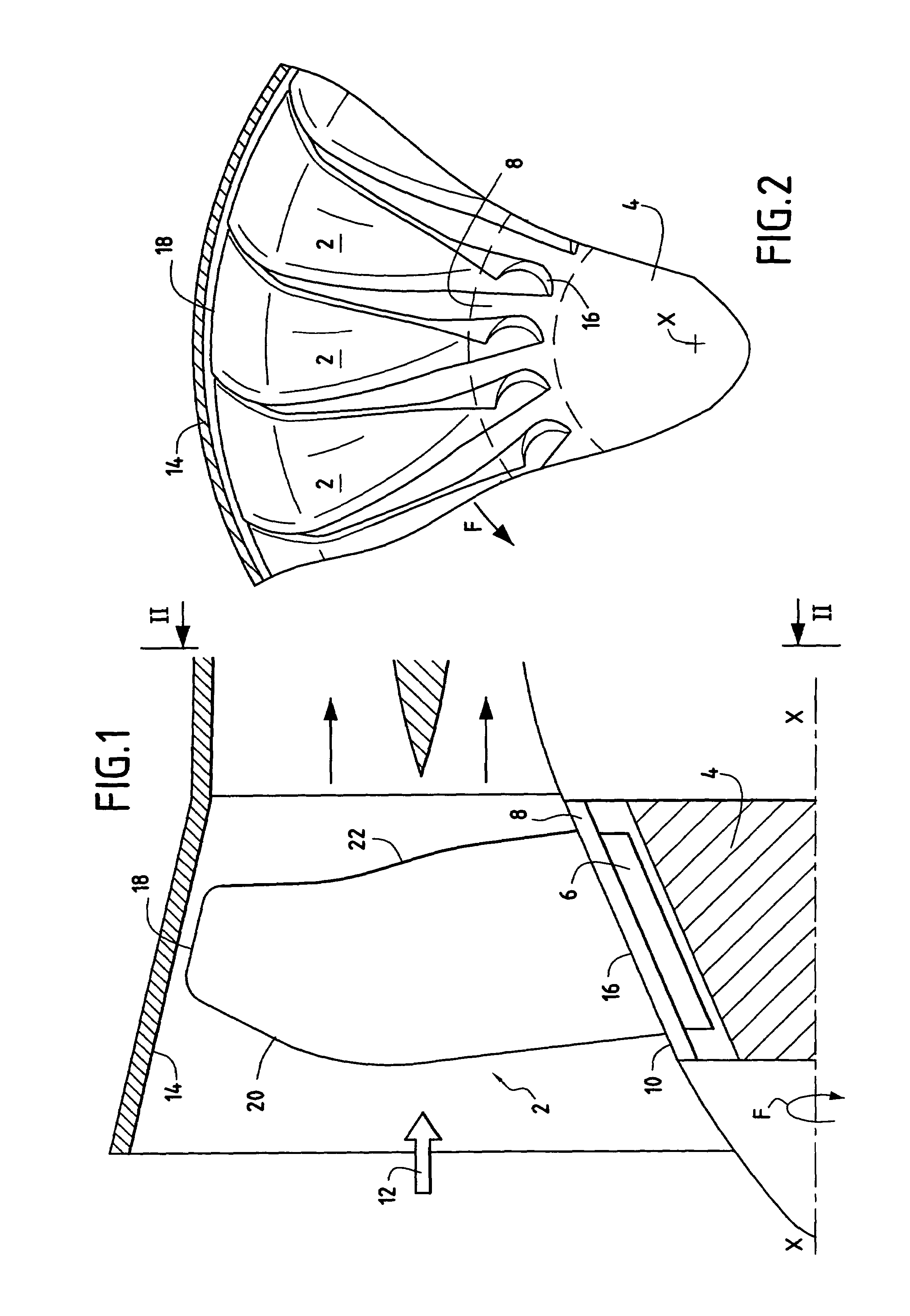
[0018]FIGS. 1 and 2 are fragmentary and diagrammatic longitudinal and cross-sectional views of a turbojet fan fitted with blades constituting an embodiment of the invention. In the figures, the fan comprises a row of blades 2 that are regularly spaced apart from one another around a disk or hub 4. Each blade 2 is fixed to the disk or hub 4 by means of a root 6, which disk or hub 4 rotates about a longitudinal axis X—X of the turbojet in the direction of rotation indicated by arrow F. Each blade 2 also has a platform 8 which extends part of the way around the longitudinal axis X—X. When the blades are assembled on the disk or hub 4, the platforms 8 of adjacent blades come into mutual contact so as to define an inside wall 10 for an airflow stream 12 passing through the fan. A wall 14 of a casing surrounding the fan forms the outside wall of the airflow stream.

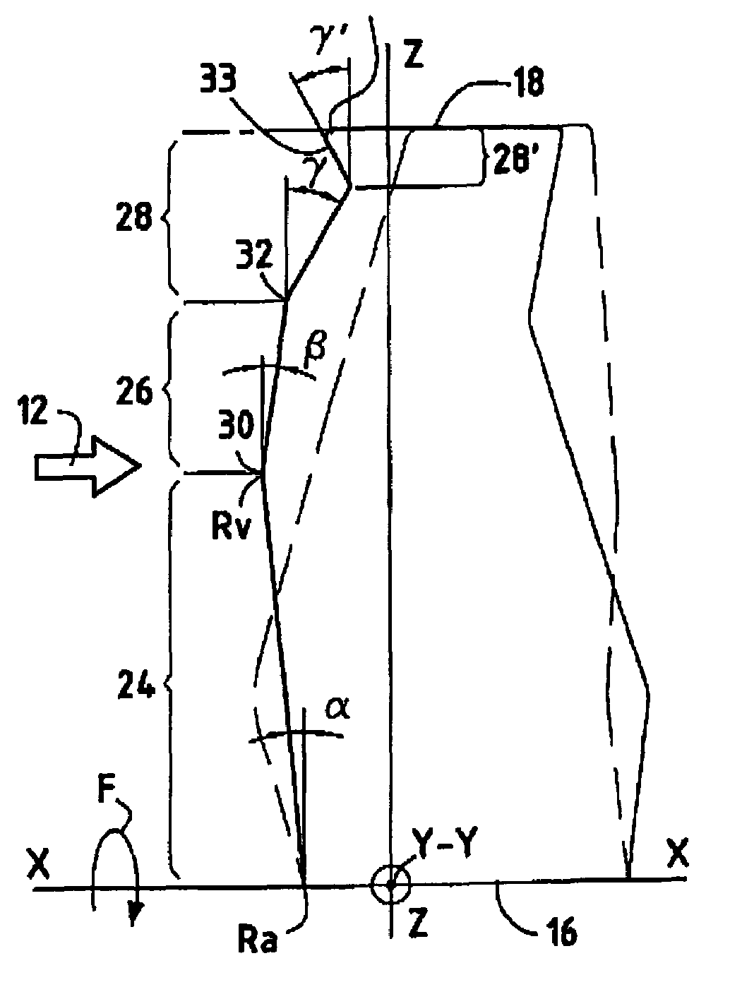
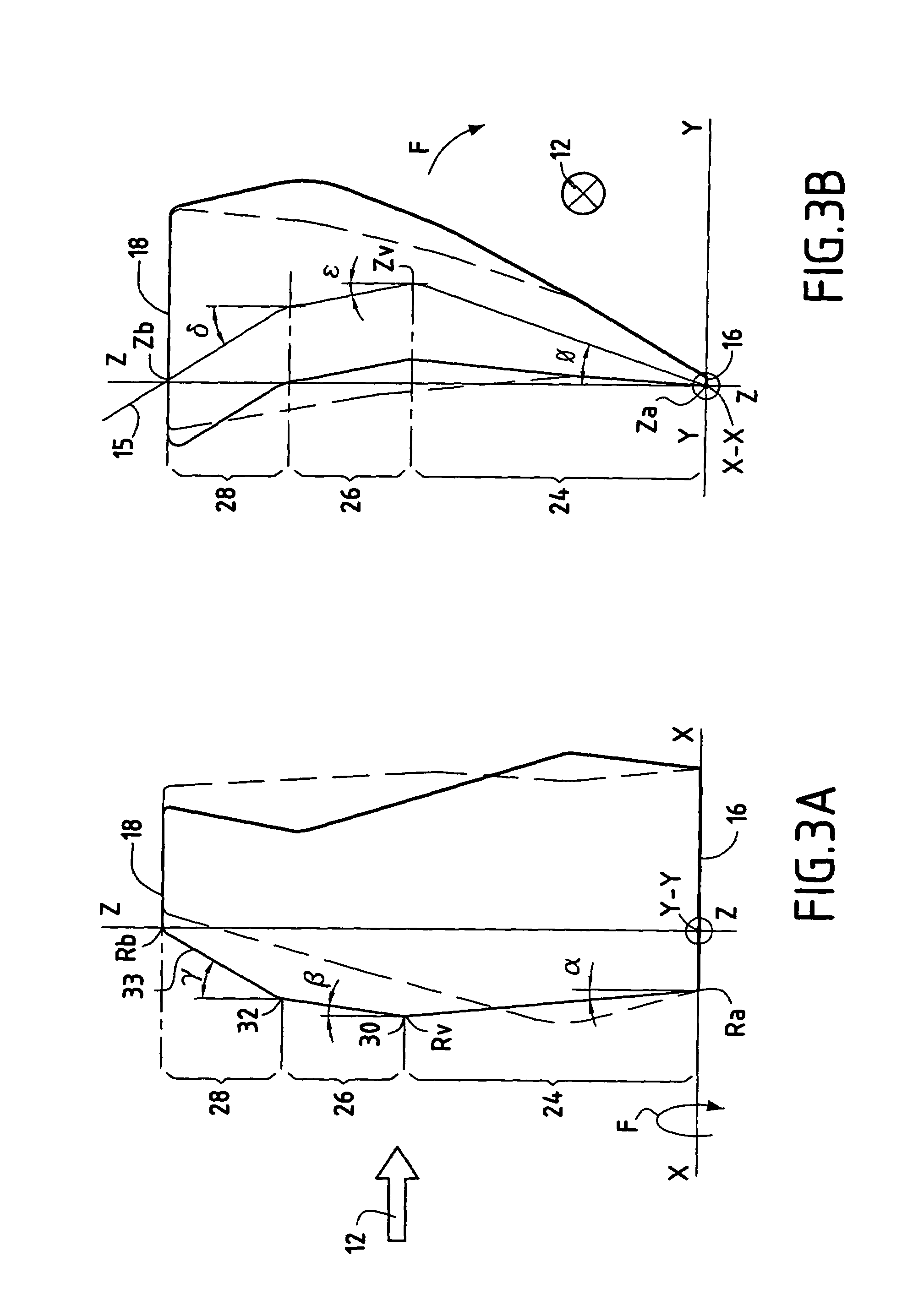
[0019]For the description below, the radial axis Z—Z of the turbojet is defined as being the axis perpendicular to the longitu...


PUM


Abstract

A rotary turbojet blade comprises a plurality of blade sections extending along a line of the centers of gravity of said sections between a base and a tip, said blade presenting along a radial axis a bottom portion, an intermediate portion, and a top portion, said bottom portion presenting a longitudinal angle of inclination for a leading edge line, said intermediate portion presenting a backward longitudinal angle of inclination for said leading edge line, and said top portion presenting a backward longitudinal angle of inclination for said leading edge line and a tangential angle of inclination for said line of the centers of gravity in a direction opposite to the direction of rotation of said blade.

Description

BACKGROUND OF THE INVENTION[0001]The present invention relates to the general field of backswept blades for turbojets. More particularly, the invention relates to the geometry of blades in the fan or the compressors of a turbojet.[0002]A turbojet is provided in particular with a fan followed, in the flow direction of the gases passing through the turbojet, by a multistage compressor. The fan and the compressor are elements of the turbojet through which the gas flow passes. Each of them comprises a row of moving blades that are circumferentially spaced apart from one another so as to define passages for the gas flow. The blades of these elements are subjected to speeds of rotation that can generate subsonic to supersonic speeds in the flow of gas passing through these elements of the turbojet. Although high flow speeds make it possible in particular to improve the mass flow rate of the gas, thereby increasing the thrust of the turbojet, they can also sometimes present the drawback of...

Claims


Application Information

Patent Timeline
Patent Type & Authority Patents(United States)
IPC IPC(8): F04D29/38F02C3/06F01D5/14F02C1/00F04D29/32F04D29/66
CPCF01D5/141F04D29/324F05D2250/20Y02T50/673Y02T50/60
Inventor TALBOTEC, JEROMEFESSOU, PHILIPPEJOLY, HERBERTBOIS, BEATRICE
Owner SN DETUDE & DE CONSTR DE MOTEURS DAVIATION S N E C M A
Why Eureka
Try Eureka