Flat antenna, antenna unit and broadcast reception terminal apparatus

Inactive Publication Date: 2006-09-19
SONY CORP
View PDF5 Cites 43 Cited by
  • Summary
  • Abstract
  • Description
  • Claims
  • Application Information

AI Technical Summary

Benefits of technology

[0018]Therefore, by configuring an antenna unit related to the present invention so as to be capable of receiving television broadcast, it is pos

Problems solved by technology

Therefore, there is a problem in that the structure of the substrate forming the antenna inevitably becomes multi-layered, and manufacturing costs increase.
In addition, when a miniaturized antenna is configured using a high dielectric material, the resonance value of the antenna becomes extremely high, and the frequency band extremely narrow.
Therefore, when the range of frequ

Method used


Image

  • Flat antenna, antenna unit and broadcast reception terminal apparatus
  • Flat antenna, antenna unit and broadcast reception terminal apparatus
  • Flat antenna, antenna unit and broadcast reception terminal apparatus

Examples


Embodiment Construction

[0038]Hereinafter, embodiments of the present invention will be described with reference to the drawings. In these embodiments, a broadcast reception terminal, an antenna unit and a flat antenna that receive airwaves in the UHF band will be given as examples.

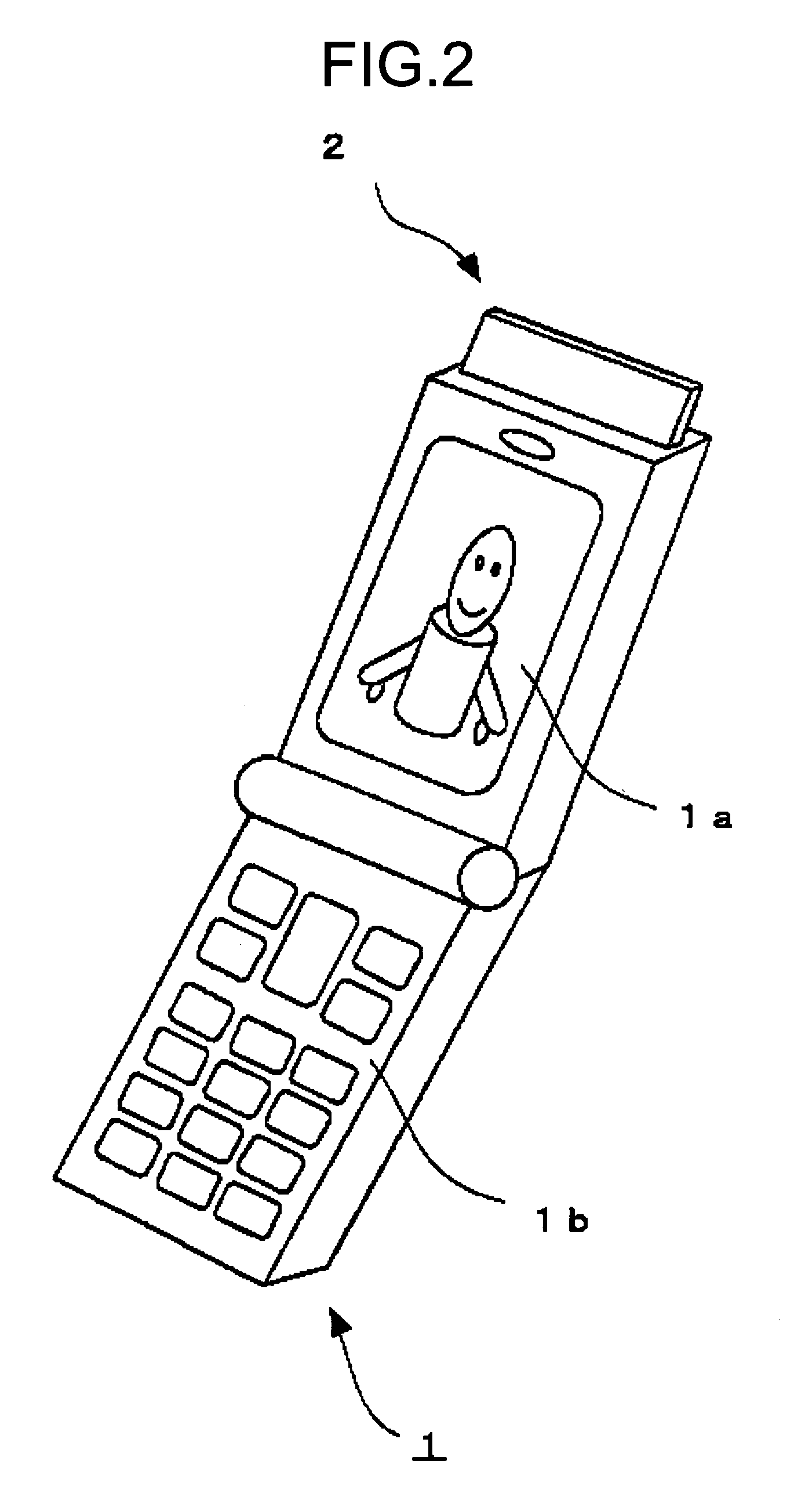
[0039]FIG. 2 is an external view of a portable terminal that is capable of receiving television broadcast in the UHF band as an embodiment of the present invention.

[0040]The portable terminal 1 shown in FIG. 2 has such a structure that an antenna unit 2 can be attached to an upper end section thereof. By attaching the antenna unit 2, television broadcast, for example, can be received and television pictures can be displayed on its display screen 1a. Channel selection can be performed through an operation section 1b.

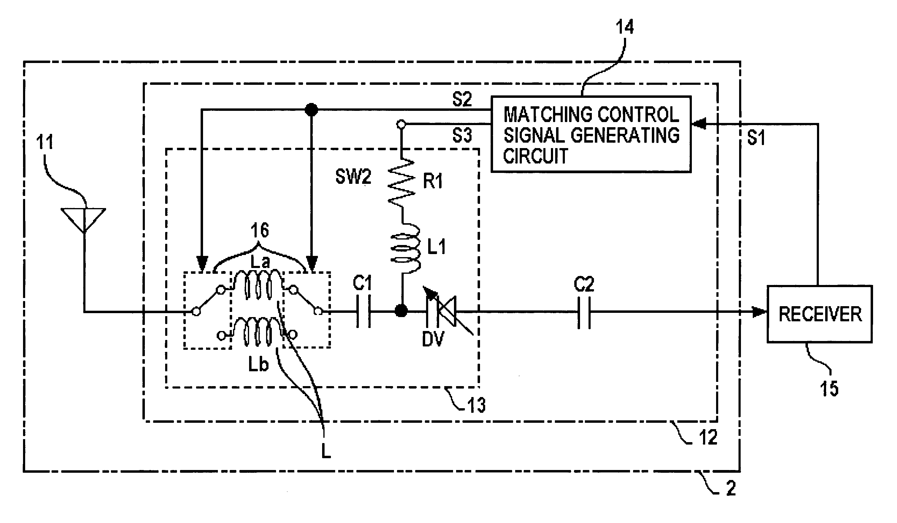
[0041]The antenna unit 2 has a flat antenna 11 for receiving at least airwaves in the VHF band and / or UHF band for television broadcast. The antenna unit 2 will be described later.

[0042]In such a portable terminal 1 ...


PUM


Abstract

There is provided a flat antenna that includes a feed conductor, and at least one non-feed conductor positioned on either one side or both sides of the feed conductor depending on the required reception band. Thus, a flat antenna that is capable of receiving television broadcast can be miniaturized. In addition, a matching circuit that is so configured that the resonant frequency of the flat antenna is made variable is provided integrally. Through this matching circuit, the resonant frequency of the flat antenna can be varied so as to correspond to the desired reception channel.

Description

CROSS REFERENCE TO RELATED APPLICATIONS[0001]The present document claims priority to Japanese Priority Documents JP 2003-012679 and JP 2003-012680, both filed in the Japanese Patent Office on Jan. 21, 2003, the entire contents of which are incorporated herein by reference to the extent permitted by law.BACKGROUND OF THE INVENTION[0002]1. Field of the Invention[0003]The present invention relates to a flat antenna, an antenna unit that is integrally equipped with matching (tuning) functions and a broadcast reception terminal apparatus, which are suitable for receiving television broadcast, for example.[0004]2. Description of Related Art[0005]As a broadcast receiver apparatus of a portable size that is capable of receiving television broadcast, there is a conventional TV broadcast reception terminal 100 as shown in FIG. 1.[0006]Ordinarily, a stick-shaped antenna 101 for receiving television broadcast in the VHF (Very High Frequency) and UHF (Ultra High Frequency) bands is attached to s...

Claims


Application Information

Patent Timeline
IPC IPC(8): H01Q1/50H01Q9/28H01Q1/24H01Q1/38H01Q1/40H05K1/16
CPCH01Q1/242H01Q1/40H01Q1/38H05K1/16
Inventor MORI, KOHEI
Owner SONY CORP
Why Eureka
Try Eureka