Self-calibrating direct conversion transmitter

a transmitter and self-calibration technology, applied in the field of communication systems, can solve the problems of i-q gain/phase imbalance problem, difficult design challenge for wireless communication device engineers, and difficult to develop such a wireless communication device, so as to improve the non-linearity, local oscillation leakage, and the effect of reducing the negative effects of imbalances within the transmitter

Inactive Publication Date: 2006-09-19
AVAGO TECH WIRELESS IP SINGAPORE PTE
View PDF4 Cites 57 Cited by
  • Summary
  • Abstract
  • Description
  • Claims
  • Application Information

AI Technical Summary

Benefits of technology

[0010]The calibration execution module is operably coupled to calibrate the DC level of the I and / or Q component of the base-band signal, and / or the gain of the I and / or Q component of the base-band signal based on the calibration signal. By calibrating the DC offset level and / or the gain of the transmitter, the adverse affects of imbalances within the transmitter are reduced. As such, local oscillation leakage, gain imbalances, non-linearities, et cetera of the transmitter are improved.

Problems solved by technology

As the demand for enhanced performance (e.g., reduced interference and / or noise, image rejection, compliance with multiple standards, compliance with multiple frequency bands, increased broadband applications, et cetera), smaller sizes, lower power consumption, and reduced costs increases, wireless communication device engineers are faced with a very difficult design challenge to develop such a wireless communication device.
However, for a direct conversion transmitter, LO pulling, RF carrier leakage due to I-Q DC offset, and I-Q gain / phase imbalance problems are more pronounced than in multistage up conversion transmitters.

Method used


Image

  • Self-calibrating direct conversion transmitter
  • Self-calibrating direct conversion transmitter
  • Self-calibrating direct conversion transmitter

Examples


Embodiment Construction

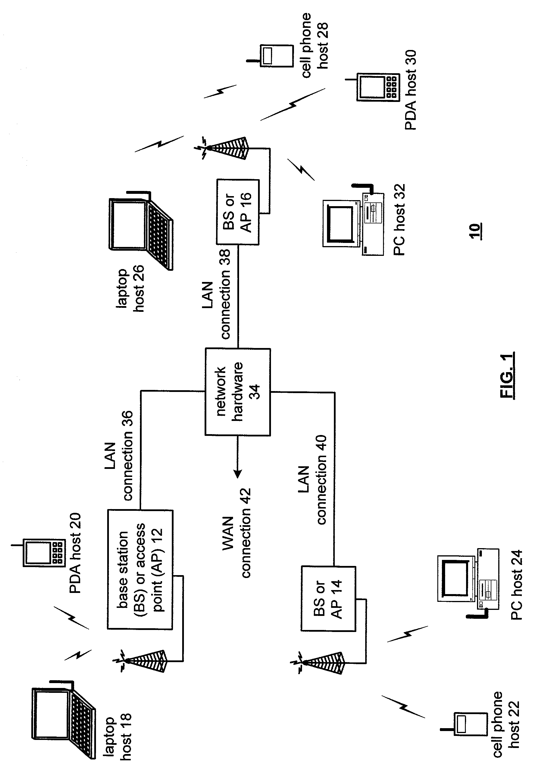
[0025]FIG. 1 illustrates a schematic block diagram of a communication system 10 that includes a plurality of base stations and / or access points 12–16, a plurality of wireless communication devices 18–32 and a network hardware component 34. The wireless communication devices 18–32 may be laptop host computers 18 and 26, personal digital assistant hosts 20 and 30, personal computer hosts 24 and 32 and / or cellular telephone hosts 22 and 28. The details of the wireless communication devices will be described in greater detail with reference to FIG. 2.

[0026]The base stations or access points 12 are operably coupled to the network hardware 34 via local area network connections 36, 38 and 40. The network hardware 34, which may be a router, switch, bridge, modem, system controller, et cetera provides a wide area network connection 42 for the communication system 10. Each of the base stations or access points 12–16 has an associated antenna or antenna array to communicate with the wireless c...


PUM


Abstract

A self-calibrating transmitter includes an up-conversion mixing module, summing module, calibration determination module, and a calibration execution module. The up-conversion mixing module is operably coupled to mix an I component of a base-band signal with an I component of a local oscillation to produce a mixed I signal and is also operably coupled to mix a Q component of the base-band signal with a Q component of the local oscillation to produce a mixed Q signal. The summing module sums the mixed I signal with the mixed Q signal to produce a modulated radio frequency (RF) signal. The calibration determination module is operably coupled to produce a calibration signal, which it generates by interpreting the local oscillation and the modulated RF signal. The calibration execution module is operably coupled to calibrate the DC level of the I and/or Q component of the base-band signal, and/or the gain of the I and/or Q component of the base-band signal based on the calibration signal.

Description

TECHNICAL FIELD OF THE INVENTION[0001]This invention relates generally to communication systems and more particularly to radio transceivers used within such communication systems.BACKGROUND OF THE INVENTION[0002]Communication systems are known to support wireless and wire lined communications between wireless and / or wire lined communication devices. Such communication systems range from national and / or international cellular telephone systems to the Internet to point-to-point in-home wireless networks. Each type of communication system is constructed, and hence operates, in accordance with one or more communication standards. For instance, wireless communication systems may operate in accordance with one or more standards including, but not limited to, IEEE 802.11, Bluetooth, advanced mobile phone services (AMPS), digital AMPS, global system for mobile communications (GSM), code division multiple access (CDMA), and / or variations thereof.[0003]Depending on the type of wireless commun...

Claims


Application Information

Patent Timeline
Patent Type & Authority Patents(United States)
IPC IPC(8): H04L27/04H04B1/40
CPCH04B1/406
Inventor SHI, HONGJENSEN, HENRIK T.
Owner AVAGO TECH WIRELESS IP SINGAPORE PTE
Why Eureka
Try Eureka