Exhaust cleaning device of internal combustion engine

a cleaning device and internal combustion engine technology, applied in the direction of exhaust treatment electric control, electrical control, separation process, etc., can solve the problems of reducing fuel efficiency, dpf temperature suddenly rises, and fuel efficiency reduction in accordance with dpf regeneration becomes low, so as to achieve sufficient learning frequency and improve the effect of learning control precision

Active Publication Date: 2006-09-26
DENSO CORP
View PDF6 Cites 105 Cited by
  • Summary
  • Abstract
  • Description
  • Claims
  • Application Information

AI Technical Summary

Benefits of technology

[0011]Considering the foregoing circumstances, an object of the present invention is to secure sufficient learning frequency and improve precision in learning control, in a system which carries out temperature control by feedback control of an exhaust temperature and the learning control.

Problems solved by technology

At this time, post injection, delay in fuel injection timing, intake throttle, or the like is used as a method for increasing the DPF temperature, but any of these methods have the problem of reduction in fuel efficiency.
Thus, reduction in fuel efficiency in accordance with the DPF regeneration becomes low.
If the DPF temperature is too high, however, the DPF temperature suddenly rises due to the sudden burn of the PM.
This present a possibility of breakage of the DPF, degradation in a catalyst supported on the DPF, and the like.
However, there is limitation in the ability to increase temperature of temperature increase means, and dispersion occurs in accordance with each operational state.
In the feedback control, there is a problem that the dispersion in temperature exacerbates control performance.
In this method, however, there is a problem that learnable operational states are limited.
Thus, it is impossible to detect the dispersion in temperature from the correction amount in the transient state and, hence, it is necessary to learn the correction amount in a state where the exhaust temperature sufficiently stabilizes with respect to the operational state and the amount of temperature increase operation.
Variation in the exhaust temperature with respect to variation in the operational state and the amount of temperature increase operation is extremely sluggish (for example, 63% response takes 5 to 60 seconds).
When the learnable operational state is limited to the steady state, as described above, it is impossible to obtain sufficient learning frequency and, hence, learning with high precision becomes difficult.

Method used


Image

  • Exhaust cleaning device of internal combustion engine
  • Exhaust cleaning device of internal combustion engine
  • Exhaust cleaning device of internal combustion engine

Examples


Embodiment Construction

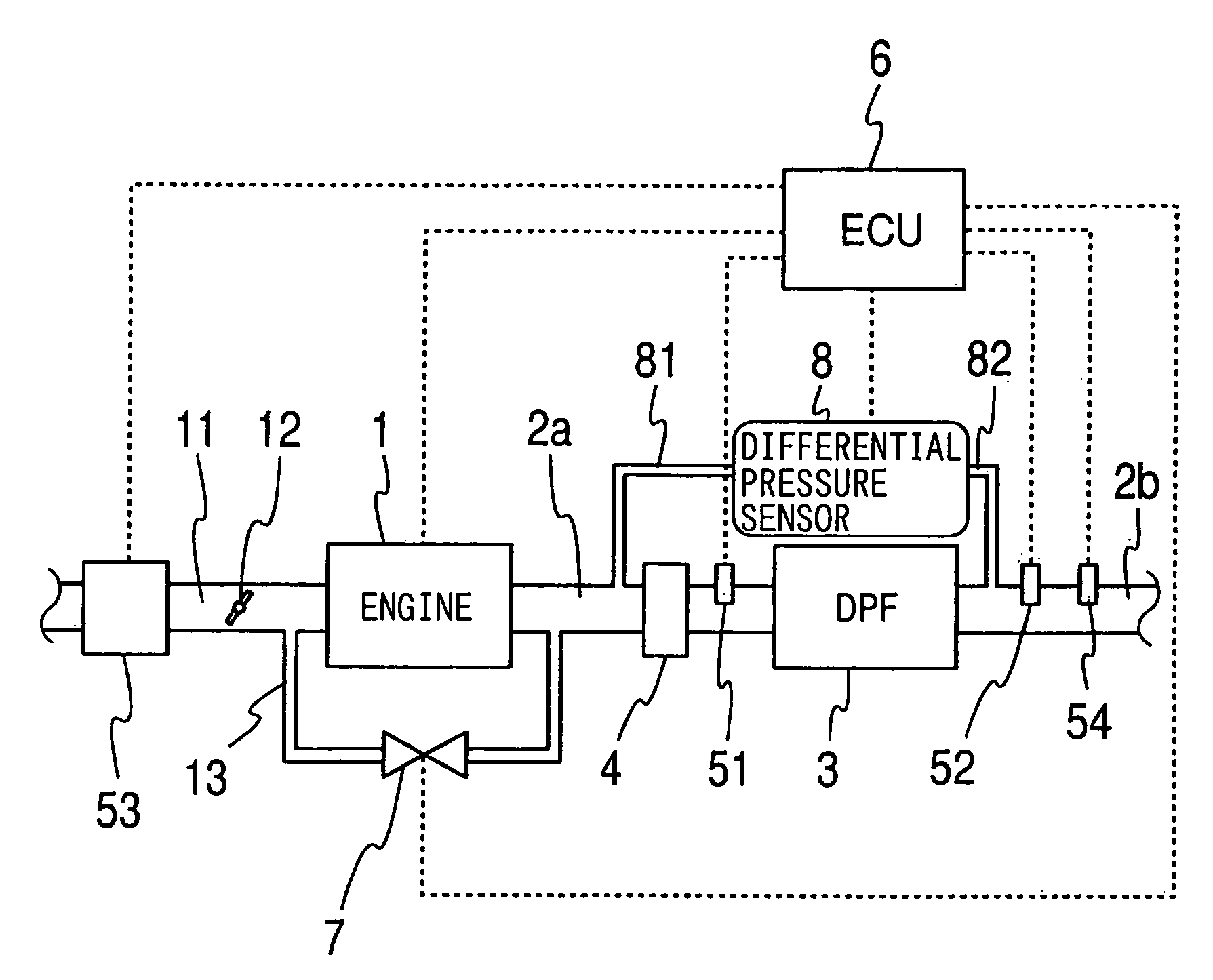
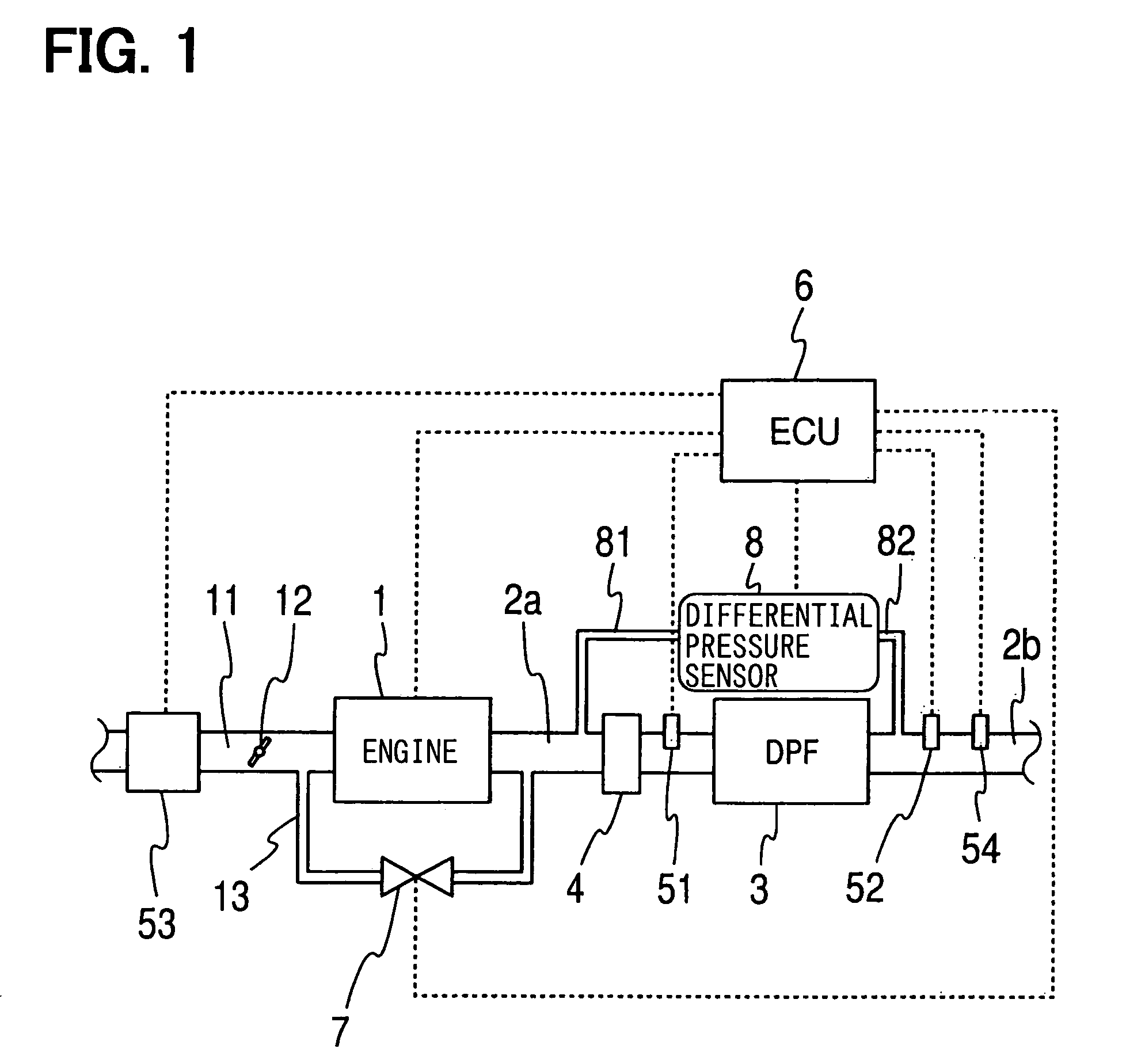
[0050]A first embodiment of an exhaust cleaning device of a diesel engine to which the present invention is applied will be hereinafter described. FIG. 1 shows an example of the structure of a system. An oxidation catalyst (DOC) 4 is disposed upstream of a diesel particulate filter (DPF) 3. The DPF 3 is disposed between exhaust ducts 2a and 2b of a diesel engine 1, and the DOC 4 is disposed in the exhaust duct 2a a upstream of the DPF 3. The DPF 3 is a ceramic filter with well-known structure. In the DPF 3, for example, heat-resistant ceramic such as cordierite is molded into honeycomb structure, and many cells being gas passages are sealed in such a manner that inlets or outlets are alternate with one another. While exhaust ejected from the engine 1 flows downstream through porous partition walls of the DPF 3, particulates (PM) are collected and gradually accumulated.

[0051]In the DOC 4 with a well-known structure, the oxidation catalyst is supported on the surface of a ceramic carr...


PUM

PropertyMeasurementUnit
temperatureaaaaaaaaaa

Abstract

An exhaust cleaning device of an internal combustion engine includes a particulate filter disposed in an exhaust duct of the internal combustion engine. A regeneration control increases the temperature of the particulate filter to approximately a predetermined target temperature but the amount of the temperature increase controllably corrected by the regeneration control.

Description

CROSS REFERENCE TO RELATED APPLICATIONS[0001]This application is based upon and claims the benefit of priority of Japanese Patent Application No. 2004-135249, filed on Apr. 30, 2004, the contents of which are incorporated herein by reference.FIELD OF THE INVENTION[0002]The present invention relates to an exhaust cleaning device of an internal combustion engine in which a particulate filter is provided in an exhaust duct and, more particularly, a device that relates to a temperature increase control process of the particulate filter.BACKGROUND OF THE INVENTION[0003]There is a known exhaust cleaning device which is provided with a particulate filter (hereinafter abbreviated as DPF) for collecting particulates (hereinafter abbreviated as PM) ejected from a diesel engine. In such a device, a DPF temperature is increased to, for example, 600 degrees centigrade or more when the amount of PM accumulated on the DPF reaches a predetermined value, in order to burn and remove the PM on the DPF...

Claims


Application Information

Patent Timeline
Patent Type & Authority Patents(United States)
IPC IPC(8): F01N3/00F02D45/00B01D46/42B01D53/86B01D53/94F01N3/02F01N3/023F01N3/025F01N3/035F01N3/18F01N3/24F01N9/00F01N11/00F01N13/02F02D41/02F02D41/04F02D41/14F02D41/24F02D41/30
CPCF01N3/0253F01N13/009F01N9/002F02D41/029F02D41/2451F01N3/035F01N9/005F01N2250/02F02D41/1401F02D41/1446F02D41/405F02D2041/1431F02D2041/1433F02D2200/0802F02D2200/0804F02D2200/0812Y02T10/47Y02T10/40
Inventor OKUGAWA, SHINICHIROKOJIMA, KAZUO
Owner DENSO CORP
Why Eureka
Try Eureka