Minimally invasive mitral valve repair method and apparatus

a mitral valve and minimally invasive technology, applied in the field of repair of heart valves, can solve the problems of less than perfect understanding, complicated selection of appropriate repair techniques, and difficulty in ensuring the correct repair of the mitral valve, and achieves the effect of not always optimum coaptation of the leaflets in the surrounding annulus and less than perfect understanding

Inactive Publication Date: 2006-09-26
EDWARDS LIFESCIENCES CORP
View PDF99 Cites 431 Cited by
  • Summary
  • Abstract
  • Description
  • Claims
  • Application Information

AI Technical Summary

Problems solved by technology

A less than perfect understanding of the disease process leading to mitral valve regurgitation complicates selection of the appropriate repair technique.
Though implantation of an annuloplasty ring, typically around the posterior aspect of the mitral valve, has proven successful in a number of cases, shaping the surrounding annulus does not always lead to optimum coaptation of the leaflets.
As the procedure is done on a beating heart, and the pressures and motions within the left ventricle are severe, the procedure is thus rendered fairly skill-intensive.

Method used


Image

  • Minimally invasive mitral valve repair method and apparatus
  • Minimally invasive mitral valve repair method and apparatus
  • Minimally invasive mitral valve repair method and apparatus

Examples


Embodiment Construction

Exemplary Stabilizing Devices

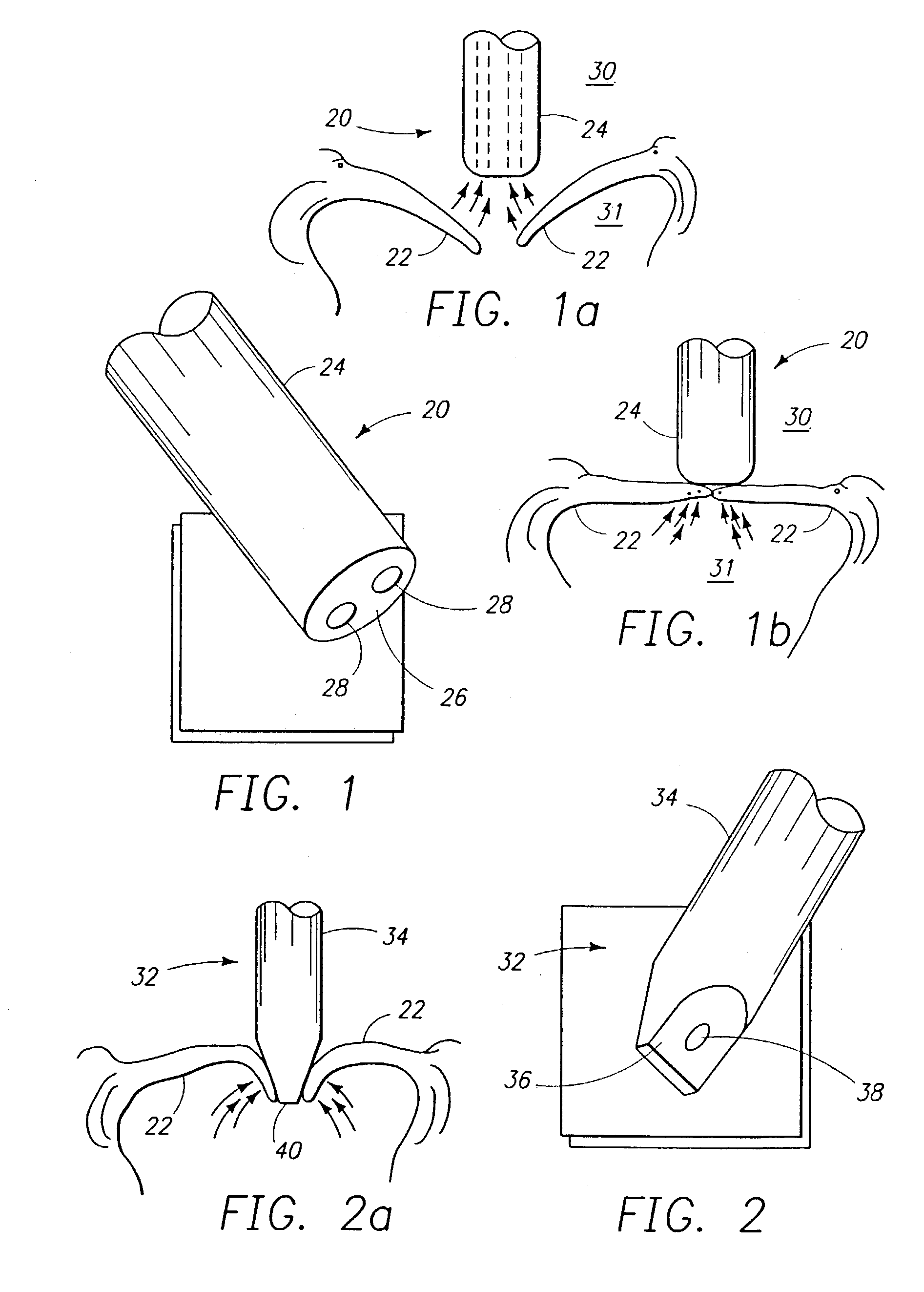
[0086]FIG. 1 shows a tissue stabilizer 20 of the present invention that uses a vacuum to hold two tissue pieces. In this case, the tissue pieces are heart valve leaflets 22 and a valve repair procedure using the stabilizer 20 is depicted in FIGS. 1a and 1b. The tissue stabilizer 20 comprises a cylindrical probe 24 with at least one internal lumen (not shown) and having a flat distal end 26, a pair of vacuum ports 28 being disposed in the distal end 26. The ports 28 may be in communication with a common vacuum source, may be separately communicable with the source with internal valves (not shown), or may be in communication with different vacuum sources. The size of the ports 28 and magnitude of suction applied may vary depending on the application, but the ports 28 are desirably spaced apart a minimum distance to create two distinct suctions. In this manner, one leaflet or the other may be stabilized with one of the ports 28 without unduly influencing th...


PUM


Abstract

The present invention is directed to an apparatus and method for the stabilization and fastening of two pieces of tissue. A single device may be used to both stabilize and fasten the two pieces of tissue, or a separate stabilizing device may be used in conjunction with a fastening device. The stabilizing device may comprise a probe with vacuum ports and / or mechanical clamps disposed at the distal end to approximate the two pieces of tissue. After the pieces of tissue are stabilized, they are fastened together using sutures or clips. One exemplary embodiment of a suture-based fastener comprises a toggle and suture arrangement deployed by a needle, wherein the needle enters the front side of the tissue and exits the blind side. In a second exemplary embodiment, the suture-based fastener comprises a needle connected to a suture. The needle enters the blind side of the tissue and exits the front side. The suture is then tied in a knot to secure the pieces of tissue. One example of a clip-based fastener comprises a spring-loaded clip having two arms with tapered distal ends and barbs. The probe includes a deployment mechanism which causes the clip to pierce and lockingly secure the two pieces of tissue.

Description

CROSS REFERENCE TO A RELATED PATENT APPLICATION[0001]The present application is a continuation of U.S. application Ser. No. 09 / 562,406, filed May 1, 2000 now U.S. Pat. No. 6,626,930, entitled Minimally Invasive Mitral Valve Repair Method and Apparatus, which claimed priority under 35 U.S.C. §119(e) from U.S. Provisional Patent Application No. 60 / 161,296, filed Oct. 21, 1999, entitled “Minimally Invasive Mitral Valve Repair Method And Apparatus”. The disclosure of both the Parent and Provisional patent application are incorporated by reference herein in its entirety.FIELD OF THE INVENTION[0002]The present invention relates to the repair of heart valves, and, more particularly, to methods and apparatuses for the repair of heart valves by fastening the valve leaflets together at their coapting edges.BACKGROUND OF THE INVENTION[0003]In vertebrate animals, the heart is a hollow muscular organ having four pumping chambers: the left and right atria and the left and right ventricles, each p...

Claims


Application Information

Patent Timeline
Patent Type & Authority Patents(United States)
IPC IPC(8): A61B17/10A61B19/00A61B17/08A61B17/00A61B17/04A61B17/06A61B17/064A61B17/068A61B17/122A61B17/30
CPCA61B17/0401A61B17/062A61B17/0482A61B17/064A61B17/068A61B17/0469A61B17/122A61B17/1227A61B2017/00243A61B2017/00783A61B2017/0417A61B2017/0458A61B2017/0464A61B2017/047A61B2017/0472A61B2017/06057A61B2017/0641A61B2017/306A61F2/246
Inventor ALLEN, WILLIAM J.BACHMAN, ALAN B.REED, SCOTTADAMS, LELAND R.STECKEL, ROBERT R.
Owner EDWARDS LIFESCIENCES CORP
Why Eureka
Try Eureka