System and method for connecting security systems to a wireless device

a wireless communication and security system technology, applied in the field of security systems, can solve problems such as depleting police resources, affecting the credibility of systems that appear to repeatedly malfunction, and high false alarm rates in communities

Inactive Publication Date: 2006-09-26
ALARM COM INC
View PDF22 Cites 776 Cited by
  • Summary
  • Abstract
  • Description
  • Claims
  • Application Information

AI Technical Summary

Benefits of technology

[0013]According to another embodiment of the present invention, the system of the present invention provides a wireless communication device at a home security system which relays a wireless communication from the home security device directly to the user's desired devices in such a way so that power failures and other power cutoff situations do not prevent the relay of information to the owner and other points of contact.

Problems solved by technology

High false alarm rates pose a serious problem in communities.
False alarms deplete police resources and undermine the credibility of systems that appear to repeatedly malfunction.
As a result, alarm owners may be forced to employ expensive third party security companies to respond to alarm situations.
In such an event, an attempt to make a confirmation call to the owner at home is ineffective.
Traditional central alarm systems often fail to proactively contact a home owner while the home owner is in transit.
In addition, power failures and other power cutoffs may prevent traditional alarm systems from contacting a user in the event of an alarm situation.
Currently, home security systems offer limited services.
The industry itself has remained stagnant and inflexible.
Similar problems exist with other security systems for office buildings, cars, boats, vaults and other objects or locations.
These and other drawbacks exist with current systems.

Method used


Image

  • System and method for connecting security systems to a wireless device
  • System and method for connecting security systems to a wireless device
  • System and method for connecting security systems to a wireless device

Examples


Embodiment Construction

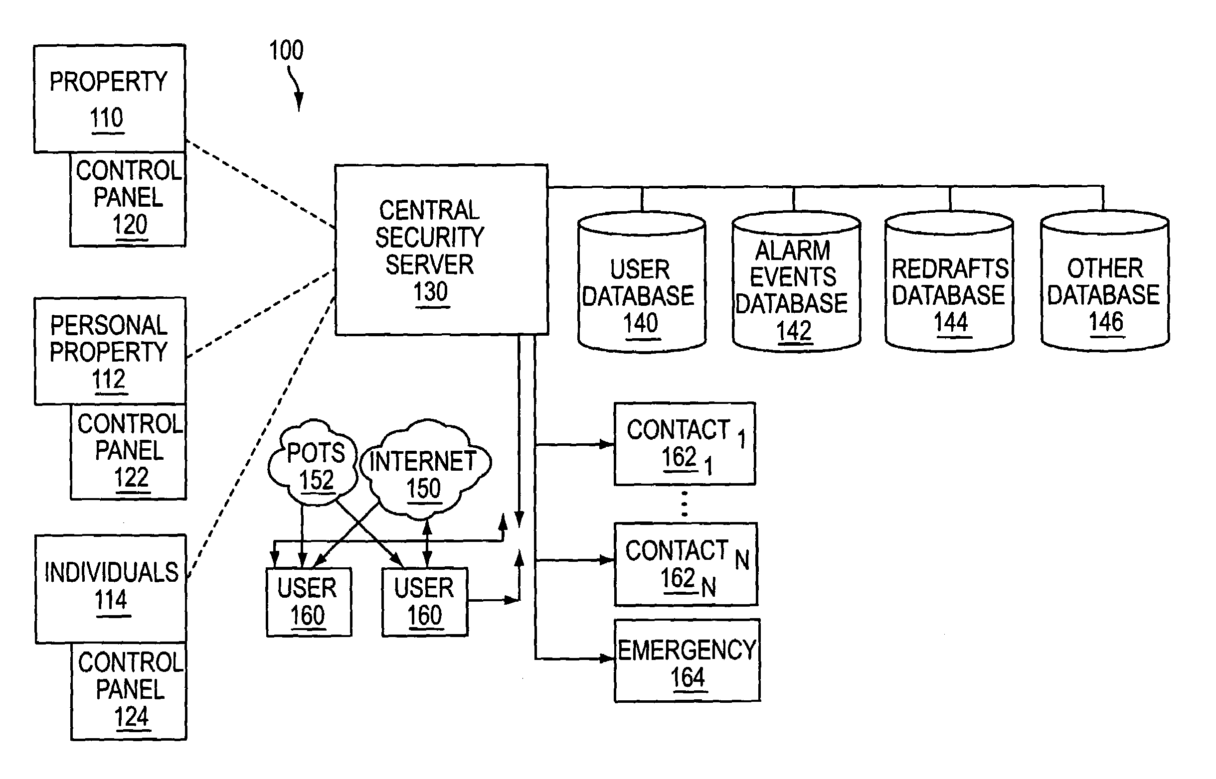
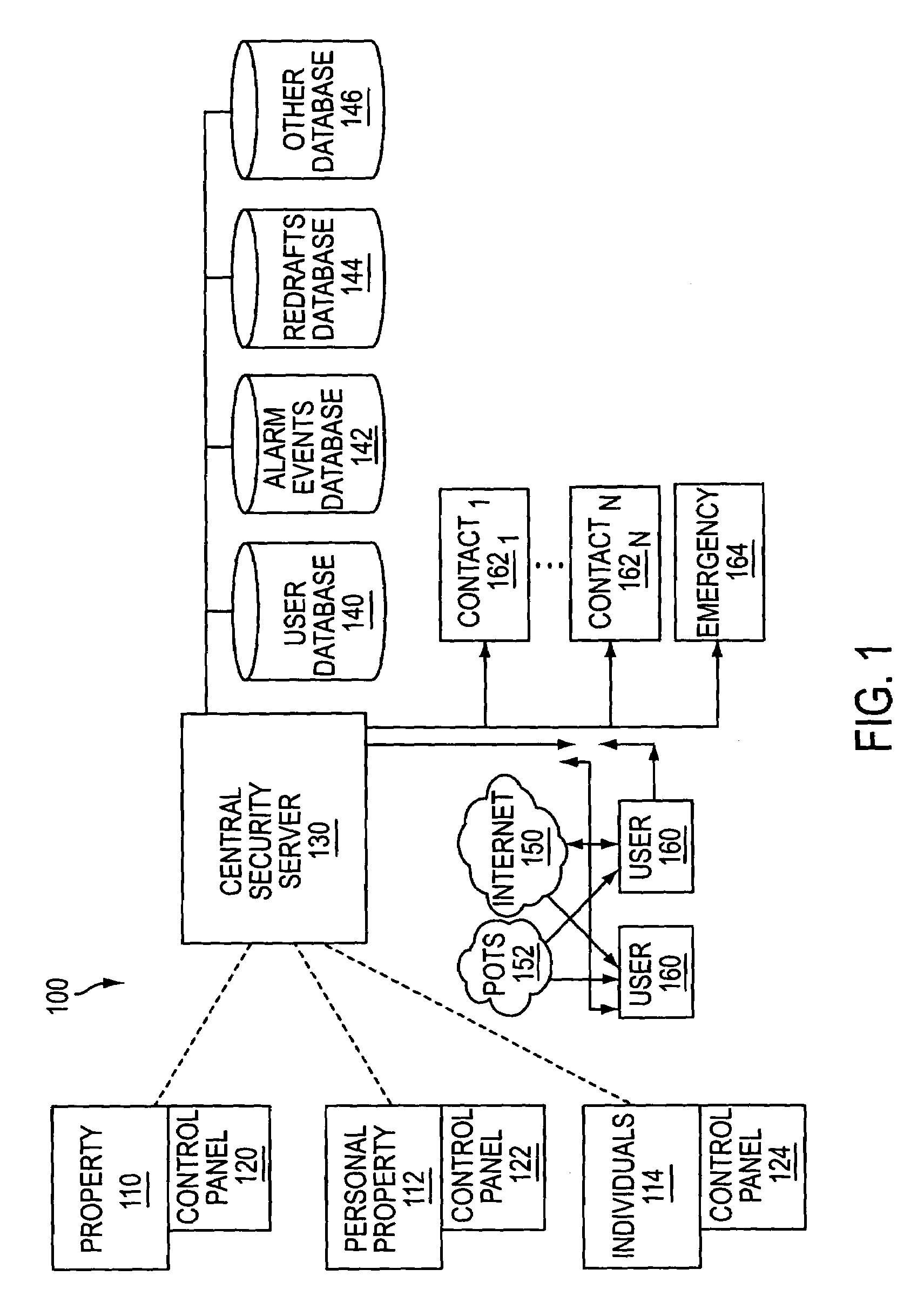
[0041]The present invention may provide a security system where a user may personalize alert notifications for various security devices and / or systems. The present invention may also provide access to a web interface (e.g., personal web page) where a user may monitor current security status and other information. Historical data may also be available for the user to generate reports based on aggregate data from security systems within the network and / or other sources of data. A user may register security devices and / or systems with the central security network of the present invention. The central security network may access the user's personal preferences, profile information and / or other information which may be used to execute notifications in the manner specified by the user. For example, the user may identify various personal preferences, which may include contact information, contact individuals, methods of communication, order of contact, special instructions and other inform...


PUM


Abstract

The present invention provides a personal security network where an individual's system or systems of security devices may be connected to a central security network. The central security network of the present invention may monitor a system's status and alert the individual when an alert situation occurs. The present invention provides a security network where a user may set up personalized alarms and alert services; identify various methods of contact; order at which to be contacted; individuals and entities to be contacted; type of situations to be alerted of and other relevant security and other information. The present invention may further provide a personalized web interface where authorized individuals may view current and historical security device status. A user may generate personalized reports based on aggregated historical data based on various user-defined factors. The reports may be displayed to the user in various formats, such as maps, graphs, statistics, and others.

Description

CROSS-REFERENCE TO RELATED APPLICATIONS[0001]This patent application is a continuation in part of U.S. patent application Ser. No. 10 / 683,299, filed Oct. 14, 2003, now U.S. Pat. No. 6,965,313, which is a continuation of U.S. patent application Ser. No. 09 / 840,302, now U.S. Pat. No. 6,661,340 B1, which are hereby incorporated by reference herein in their entirety.FIELD OF INVENTION[0002]The present invention relates generally to the field of security systems, in particular to a system and method for connecting a security system to a wireless communication system to automatically inform an owner and other authorized entities in a manner predetermined by the user when alarm situations and / or alarm worthy situations occur.BACKGROUND OF THE INVENTION[0003]Home security and personal safety are major concerns for individuals. People want to protect their valuables and provide a safe haven for family members and loved ones. Traditional home security systems generally alert neighbors and oth...

Claims


Application Information

Patent Timeline
Patent Type & Authority Patents(United States)
IPC IPC(8): G08B1/08
CPCG08B13/19682G08B13/19697G08B21/0423G08B21/0469G08B21/0476G08B21/0484G08B25/006G08B25/008G08B25/016G08B25/14G08B15/002G08B25/005G08B21/22
Inventor SAYLOR, MICHAEL J.SLAVIN, ALISONMARTIN, JEAN PAULTRUNDLE, STEPHEN SCOTT
Owner ALARM COM INC
Why Eureka
Try Eureka