
Downstream channel change technique implemented in an access network

a channel change and access network technology, applied in the field of digital computer network technology, can solve the problems of not being the most advantageous configuration for handling new and emerging broadband network applications such as video-on-demand and telephony, and not being able to provide reliable high-quality voice/video communication over such networks

Inactive Publication Date: 2006-09-26
CISCO TECH INC
View PDF4 Cites 199 Cited by
  • Summary
  • Abstract
  • Description
  • Claims
  • Application Information

AI Technical Summary

Problems solved by technology

For networks that use a shared access medium to communicate between subscribers and the service provider (e.g., cable networks, wireless networks, etc.), providing reliable high-quality voice / video communication over such networks is not an easy task.
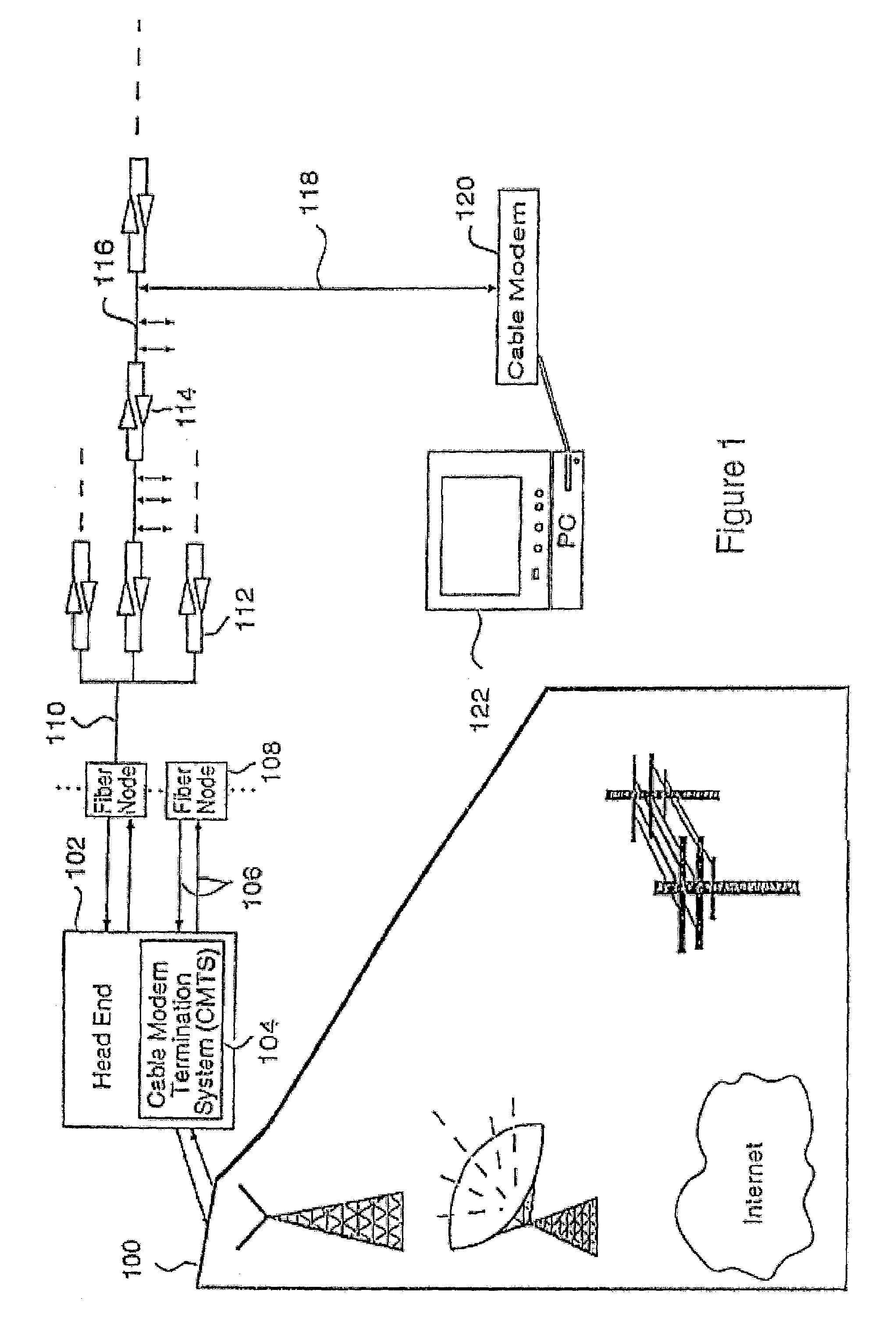
In addition, because cable modems were not used, the Head End of pre-HFC cable systems did not contain a CMTS.
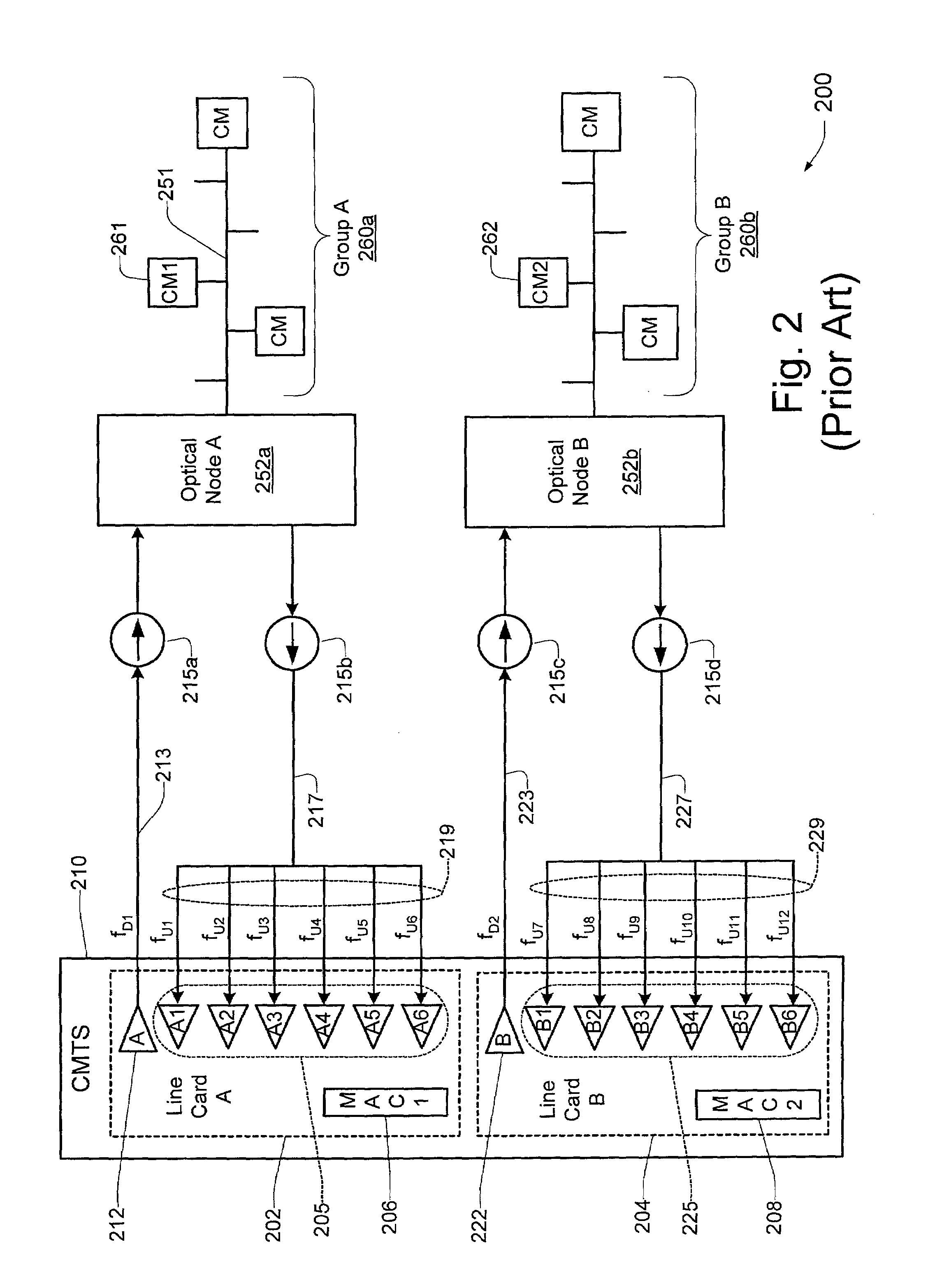
While such a configuration provides for simplicity in terms of implementation, it may not be the most advantageous configuration for handling new and emerging broadband network applications such as video-on-demand, telephony, etc.

Method used


Image

  • Downstream channel change technique implemented in an access network
  • Downstream channel change technique implemented in an access network
  • Downstream channel change technique implemented in an access network

Examples


example operation

[0131]The Dynamic Channel Change technique of the present invention will now be illustrated by way of example, with reference to FIG. 12 of the drawings and Table 1 (below). The following example describes a scenario where the CM attempts to allocate new resources by transmitting a bandwidth request to the CMTS. The CMTS temporarily rejects the request, tells the CM to change channels, and then the CM re-requests the resources. This example (not including all exception conditions) is described below, and illustrated in FIG. 12:

[0132]A) An event occurs, such as the CM issuing a bandwidth request message to the CMTS.

[0133]B) The CMTS decides that it needs to change channels in order to service this resource request. The CMTS responds with a bandwidth request response message which includes a confirmation code of “reject-temporary-DCC” in the response to indicate that the new resources are not available until a DCC is received. The CMTS now rejects any further bandwidth request message...


PUM


Abstract

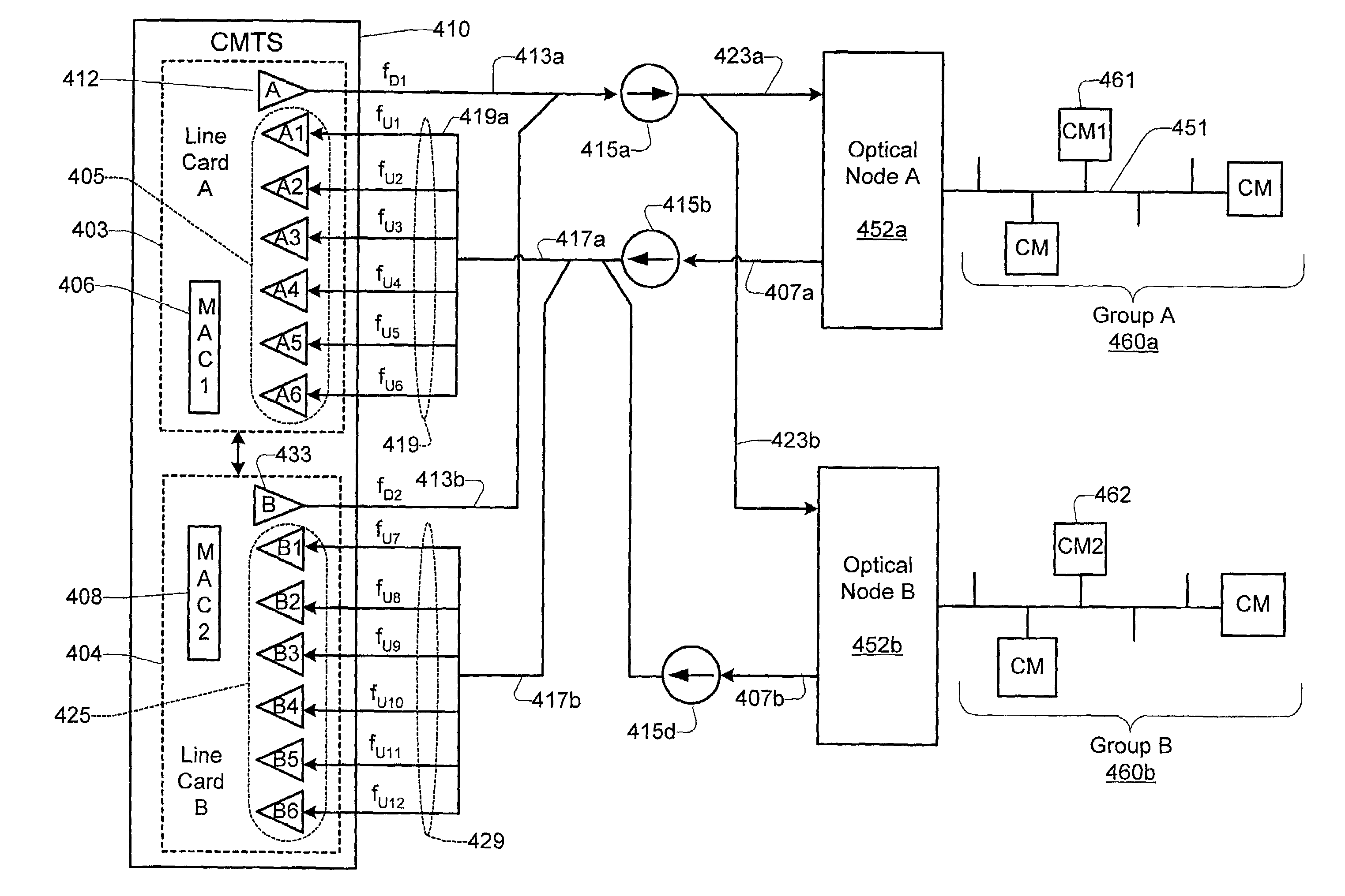
A dynamic channel change technique is disclosed which may be implemented between nodes and a Head End of an access network. Initially a network device may communicate with the Head End via a first downstream channel and a first upstream channel. When the network device receives a dynamic channel change request which includes instructions for the network device to switch to a second downstream channel, the network device may respond by switching from the first downstream channel to the second downstream channel. Thereafter, the network device may communicate with the Head End via the second downstream channel and first upstream channel. Further, according to a specific embodiment, the dynamic channel change request may also include an upstream channel change request for causing the network device to switch from a first upstream channel to a second upstream channel.

Description

RELATED APPLICATION DATA[0001]The present application claims priority under 35 USC 119(e) from U.S. Provisional patent application Ser. No. 60 / 159,085, filed on Oct. 13, 1999, and entitled “DYNAMIC CHANNEL CHANGE PROPOSAL FOR DOCSIS STANDARD”. That application is incorporated herein by reference in its entirety and for all purposes.[0002]The present application is related to U.S. patent application Ser. No. 09 / 490,761, filed on Jan. 24, 2000, and entitled, “TECHNIQUE FOR SYNCHRONIZING MULTIPLE ACCESS CONTROLLERS AT THE HEAD END OF AN ACCESS NETWORK”. That application is incorporated herein by reference in its entirety and for all purposes.BACKGROUND OF THE INVENTION[0003]This invention relates to digital computer network technology. More specifically, it relates to methods and apparatus for implementing dynamic channel changes at nodes of an access network.[0004]Broadband access technologies such as cable, fiber optic, and wireless have made rapid progress in recent years. Recently ...

Claims


Application Information

Patent Timeline
Patent Type & Authority Patents(United States)
IPC IPC(8): G01R31/08G06F11/00G08C15/00H04J1/16H04J3/14H04L1/00H04L12/26
CPCH04N21/242H04L12/2801
Inventor CHAPMAN, JOHN T.CROCKER, DANIEL W.DARUWALLA, FEISAL Y.ZANG, JOANNA QUNLU, YONG
Owner CISCO TECH INC
Learn More