Bandwidth management in a wireless network

a wireless network and bandwidth management technology, applied in the field of data communication, can solve the problems of inability to guarantee the bandwidth throughout the transmission, further exasperation,

Active Publication Date: 2006-09-26
LENOVO PC INT
View PDF21 Cites 50 Cited by
  • Summary
  • Abstract
  • Description
  • Claims
  • Application Information

AI Technical Summary

Benefits of technology

[0010]In accordance with a preferred embodiment, a method and system of managing bandwidth utilization in a wireless local area network is provided. The wireless local area network includes a plurality of clients that access the network through an access node over a wireless medium. Bandwidth utilized by each client is monitoring through the access node, and a list is dynamically maintained identifying clients that are currently exceeding a threshold level of bandwidth utilization, wherein the threshold level is determined as a function of the number of clients utilizing bandwidth through the access node. Then, the transmission of a clear-to-send signal in response to a request-to-send signal received from clients on the list is prevented.
[0011]In an alternative embodiment, a method of managing bandwidth utilization in a wireless local area network is provided, comprising monitoring the bandwidth utilized by each client through the access node; dynamically maintaining a list identifying clients that are currently exceeding a threshold level of bandwidth utilization, wherein the threshold level is determined as a function of the number of clients utilizing bandwidth through the access node, and preventing the transmission of a clear-to-send signal in response to a request-to-send signal received from clients on the list.

Problems solved by technology

This problem is further exasperated by the fact that WLAN is a data packet based technology.
For WLAN clients, data transmissions are bursty in nature, so bandwidth throughout a transmission cannot be guaranteed.

Method used


Image

  • Bandwidth management in a wireless network
  • Bandwidth management in a wireless network
  • Bandwidth management in a wireless network

Examples


Embodiment Construction

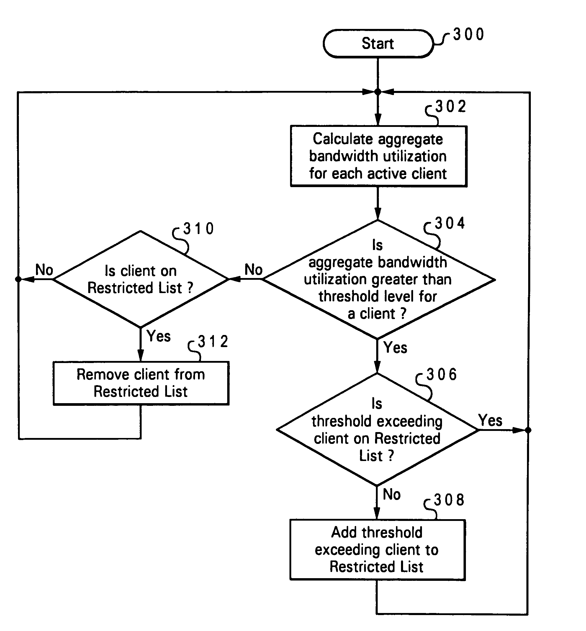
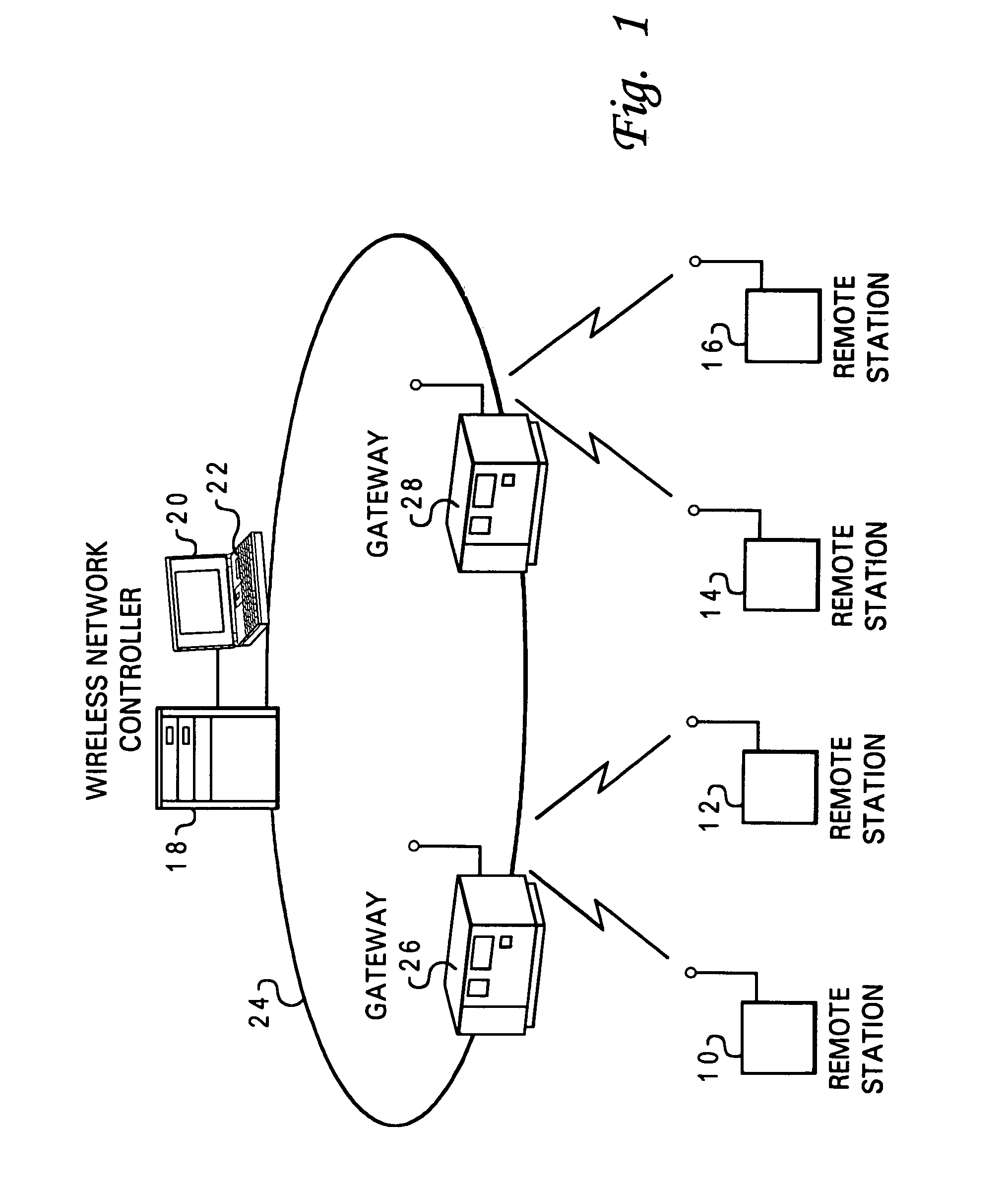
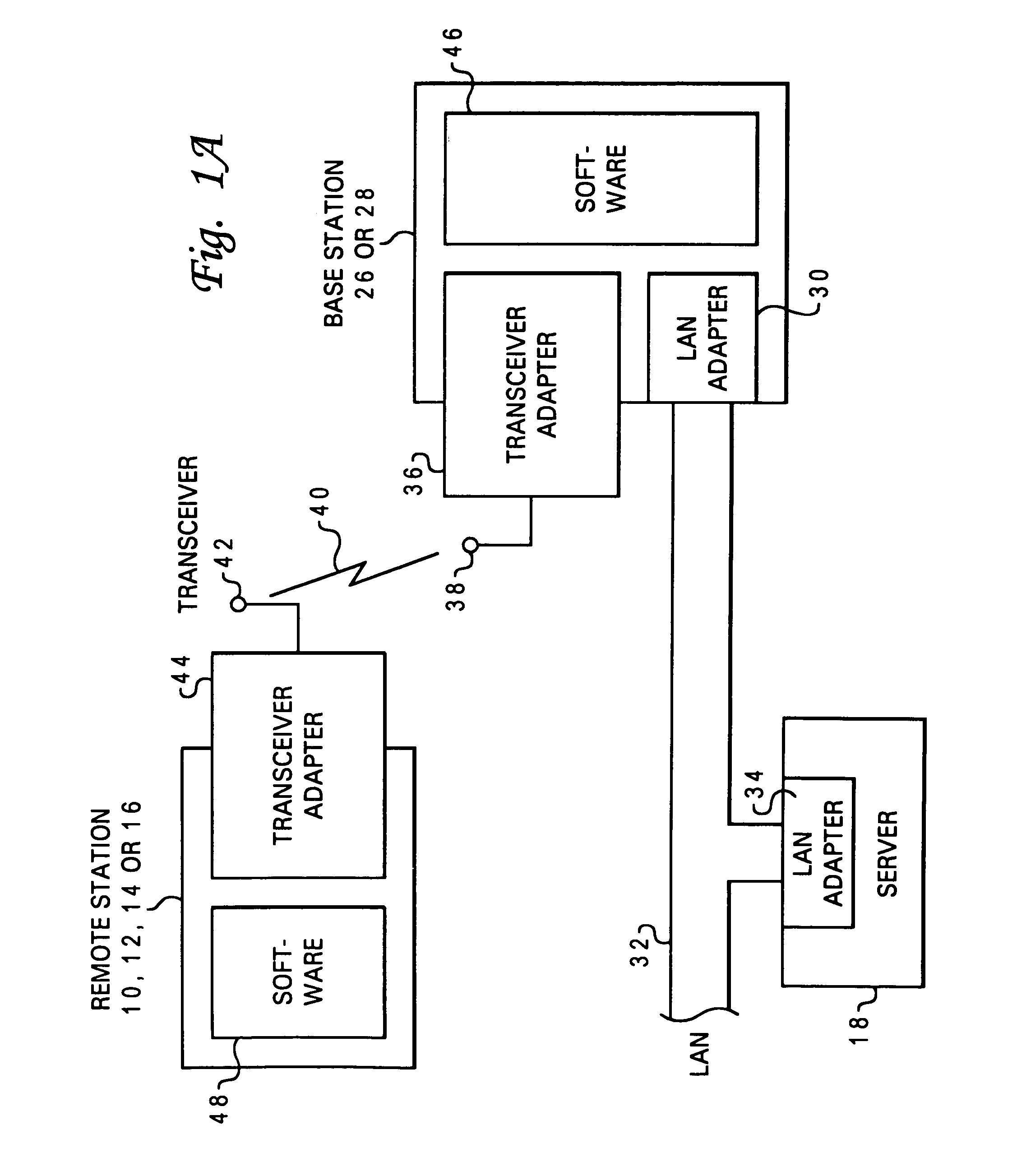
[0021]With reference now to the figures, and in particular with reference to FIG. 1, there is shown a local area radio system allowing communication between a plurality of remote stations 10, 12, 14, and 16 and applications and data residing in a computing system, and implemented in accordance with a preferred embodiment of the present invention. The computing system typically includes a Wireless Network Manager (WNM) or Wireless Network Controller (WNC) 18, (the WNM or WNC is typically a card that is inserted into a computer system) with attached monitor 20 and keyboard 22, of a local area network (LAN), generally indicated by reference numeral 24, having a plurality of attached workstations or personal computers (not shown for simplicity). Also attached to the LAN are one or more access points 26 and 28 with which the remote stations 10, 12, 14, and 16 communicate. These access points are augmented according to the invention to provide certain radio system management functions whi...


PUM


Abstract

In accordance with the preferred embodiment, an access point provides dynamic load balancing of network bandwidth between access points within the 802.11 wireless LAN. The access point uses the RTS / CTS protocol to reduce the bandwidth available to a single device using an excessive amount of network bandwidth. The access point places a device that has been monopolizing a network channel on a Restricted List, and regulates bandwidth on the network by not returning a CTS to any client on the Restricted List. When the client's network usage drops below a policy driven threshold set by the number of network users, the client is removed from the list and the access point will respond to a RTS from the client with a CTS.

Description

BACKGROUND OF THE INVENTION[0001]1. Technical Field[0002]This invention relates generally to data communications, and in particular to data communications in a Local Area Network (LAN). Specifically, the invention is directed to managing wireless access to a LAN.[0003]2. Description of the Related Art[0004]The need for personal wireless communications is expanding rapidly with the advances in digital communications and personal communications systems. The progress in wireless radio technology and the growth rate of the wireless telephone systems over the last several years is indicative of tremendous market demand for location independent communication via wireless access. Many of the current wireless networks architectures are primarily designed and optimized for voice communications and wide area coverage. With the proliferation of personal and portable computers, and local area networks, it is envisioned that data services and applications such as file server access, client-serve...

Claims


Application Information

Patent Timeline
Patent Type & Authority Patents(United States)
IPC IPC(8): H04Q7/24H04L12/28H04L12/56H04Q7/28H04H1/00H04J3/16H04J3/22H04L12/413H04H20/00H04W28/02H04W24/02H04W74/00H04W84/18
CPCH04L47/10H04L47/11H04L47/14H04L47/20H04W84/18H04W28/02H04W74/00H04W24/02H04W8/04
Inventor CROMER, DARYL CARVISJAKES, PHILIP JOHNLOCKER, HOWARD JEFFREY
Owner LENOVO PC INT
Why Eureka
Try Eureka