Location of extended linear defects

a technology of extended linear defects and defect location, applied in the field of photography, can solve the problems of affecting the image quality of the image, the length of the photographic element, the length of the photographic element, and achieve the effect of wide imaging width

Inactive Publication Date: 2006-09-26
EASTMAN KODAK CO
View PDF55 Cites 8 Cited by
  • Summary
  • Abstract
  • Description
  • Claims
  • Application Information

AI Technical Summary

Benefits of technology

[0008]The need is met according to the present invention by providing a method of locating a linear defect on a photographic element, the element having a useful imaging width and the defect aligned with length of the element, that includes the steps of: exposing a region of the element to create a latent image which is s

Problems solved by technology

Extended linear defects in scanned renditions of images on photographic elements, such as film, commonly occur.
For example, during the manufacture of photographic elements, defects in the coating process can lead to narrow regions, referred to as streaks, along the length of the photographic element in which one or more of the light-sensitive layers are affected.
Although extended linear defects can lead to undesirable artifacts in images of scenes, the effects of such defects when they occur in reference calibration images containing sensitometrically exposed patches can be even more detrimental.
um. However, the nonuniformites of interest are inherent to a recording head and not the presumably uniform medium onto which the image is recor
head. This prior art fails to repair the nonuniformity

Method used


Image

  • Location of extended linear defects
  • Location of extended linear defects
  • Location of extended linear defects

Examples


Embodiment Construction

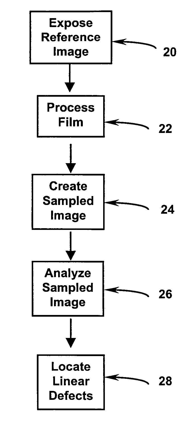
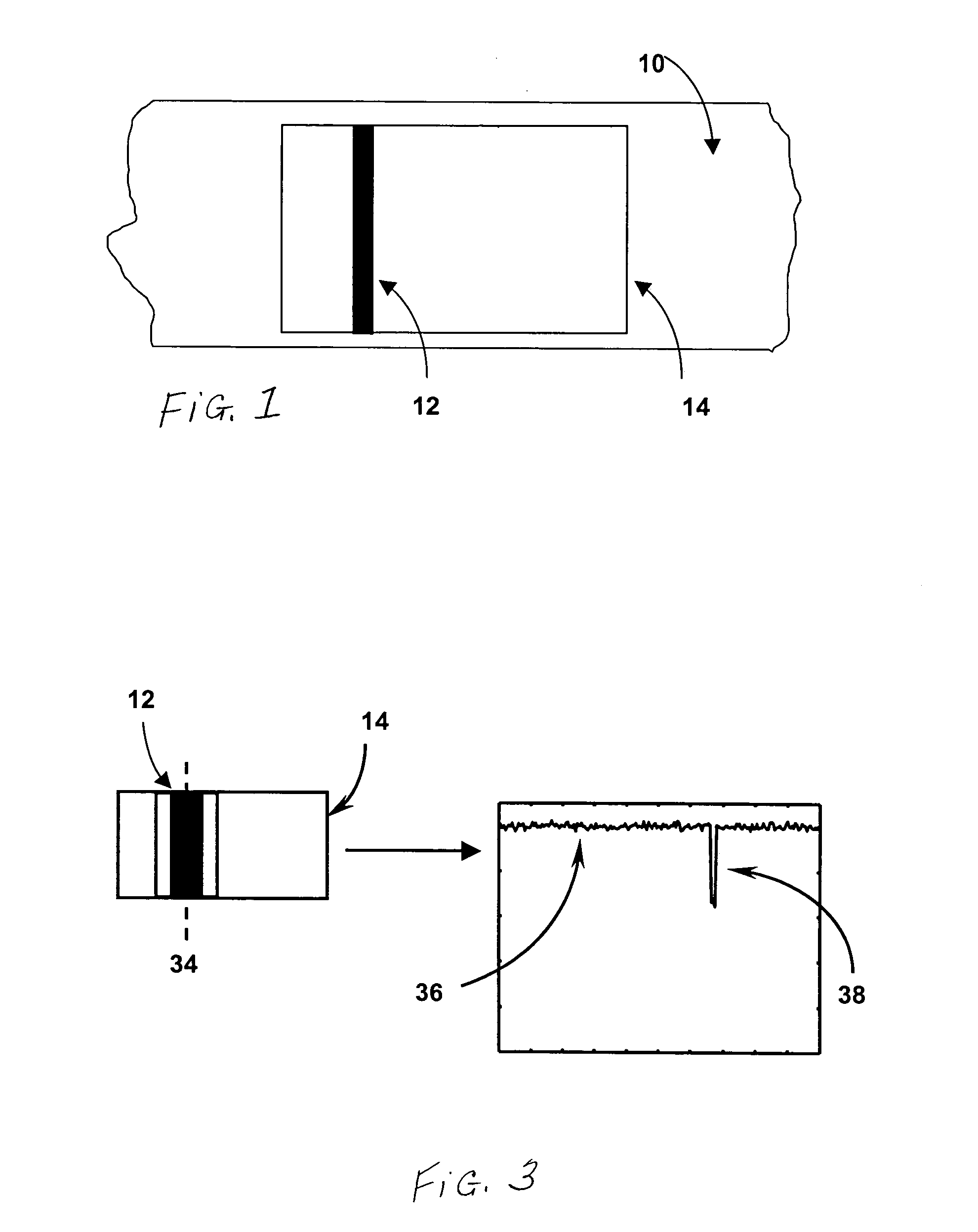
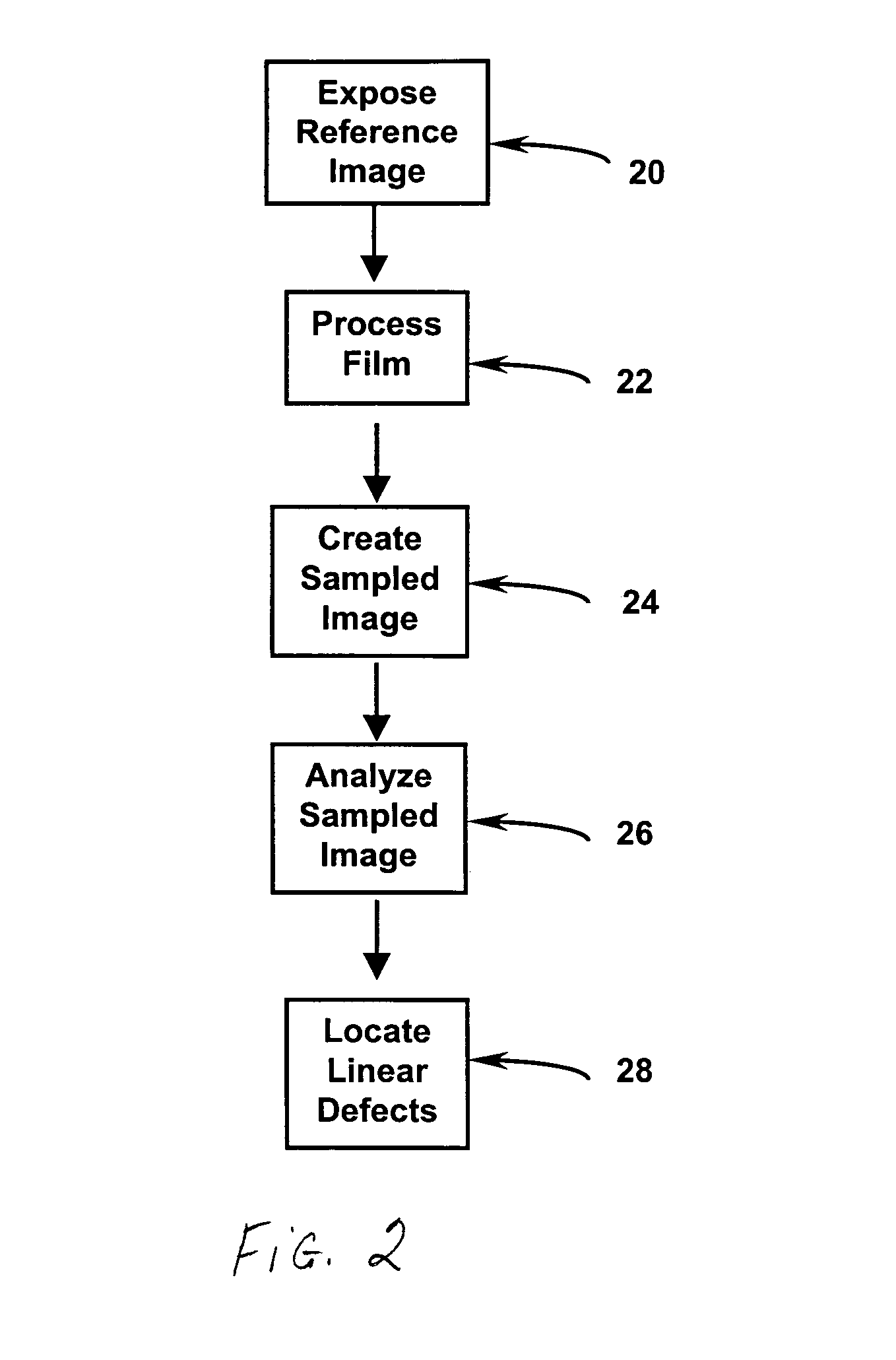
[0012]According to the present invention, a region spanning the width of a typical exposure region on a photographic element, for example the useful width of a film frame on a film strip, is exposed with a sufficiently uniform exposure.

[0013]A photographic element includes at least a base with a photosensitive layer that is sensitive to light to produce a developable latent image. The photosensitive layer may contain conventional silver halide chemistry, or other photosensitive materials such as thermal or pressure developable chemistries. It can have a transparent base, a reflective base, or a base with a magnetically sensitive coating. The photographic element can be processed through standard chemical processes, including but not limited to Kodak Processes C-41 and its variants, ECN-2, VNF-1, ECP-2 and its variants, D-96, D-97, E-4, E-6, K-14, R-3, and RA-2SM, or RA-4; Fuji Processes CN-16 and its variants, CR-6, CP-43FA, CP-47L, CP-48S, RP-305, RA-4RT; Agfa MSC 100 / 101 / 200 Film ...


PUM


Abstract

A method of locating a linear defect on a photographic element, the element having a useful imaging width and the defect aligned with length of the element, includes the steps of: exposing a region of the element to create a latent image which is substantially uniform across the useful imaging width of the element; developing the latent image to produce a density signal; sampling the density signal with a photometric device; and analyzing the sampled density data for the presence of significant deviations aligned with the length of the element to locate the defect.

Description

FIELD OF THE INVENTION[0001]The present invention relates to photography and more particularly to extended linear defect location on a photographic element in digital photofinishing applications.BACKGROUND OF THE INVENTION[0002]Extended linear defects in scanned renditions of images on photographic elements, such as film, commonly occur. Such defects include, but are not limited to scratches, digs, processing draglines, coating streakiness, coating waviness, scanner defects, etc. For example, during the manufacture of photographic elements, defects in the coating process can lead to narrow regions, referred to as streaks, along the length of the photographic element in which one or more of the light-sensitive layers are affected. Because of the affected layer or layers, there is a change in the amount of light-sensitive material and / or coupler in the streak region. This manifests itself in abnormal characteristic data in the streak region. In a second example, a dirt particle in a c...

Claims


Application Information

Patent Timeline
IPC IPC(8): G06K9/00G03C1/765H04N1/00H04N1/409
CPCH04N1/4097H04N1/00132
Inventor CAHILL, NATHAN D.SPENCE, JOHN P.
Owner EASTMAN KODAK CO
Why Eureka
Try Eureka