
Method and device to improve backlight uniformity

a backlight and uniformity technology, applied in waveguides, instruments, optical radiation measurement, etc., can solve the problems of limiting the ability to provide a uniformly lit light source to the display or keypad, affecting the uniformity of backlighting, and requiring tradeoffs or compromises in achieving proper and sufficient optical performance. , to achieve the effect of uniform image and reduce hot spot brightness

Active Publication Date: 2006-09-26
MALIKIE INNOVATIONS LTD
View PDF6 Cites 19 Cited by
  • Summary
  • Abstract
  • Description
  • Claims
  • Application Information

AI Technical Summary

Benefits of technology

The invention presents a way to make sure that a keypad or display is uniformly lit up in a space-constrained device or system. It uses a simple light guide and a hot spot filter, which can be a separate layer or patterns applied to the light guide surface. The hot spot filter is created by capturing an image of the illuminated light guide and measuring the data to create a mask that is applied to the light guide surface. This results in a uniform light output from the top surface of the light guide module. Alternatively, the image content of the LCD can be dynamically changed to cover up or compensate for hot spots. Overall, this invention provides a way to ensure consistent and high-quality lighting in space-constrained devices or systems.

Problems solved by technology

When developing an LCD or keypad lighting system, many challenges are encountered that limit the ability to provide a uniformly lit light source to the display or keypad.
For example, constraints on the x, y, and z size of the backlight system require tradeoffs or compromises in achieving proper and sufficient optical performance.
Option (2) may be cost prohibitive.
Option (3) in which creating a complex pattern is formed on the light guide, using current techniques, may increase the price of the light guide, extend the development time, and require difficult and / or expensive tooling for manufacture.

Method used


Image

  • Method and device to improve backlight uniformity
  • Method and device to improve backlight uniformity
  • Method and device to improve backlight uniformity

Examples


Embodiment Construction

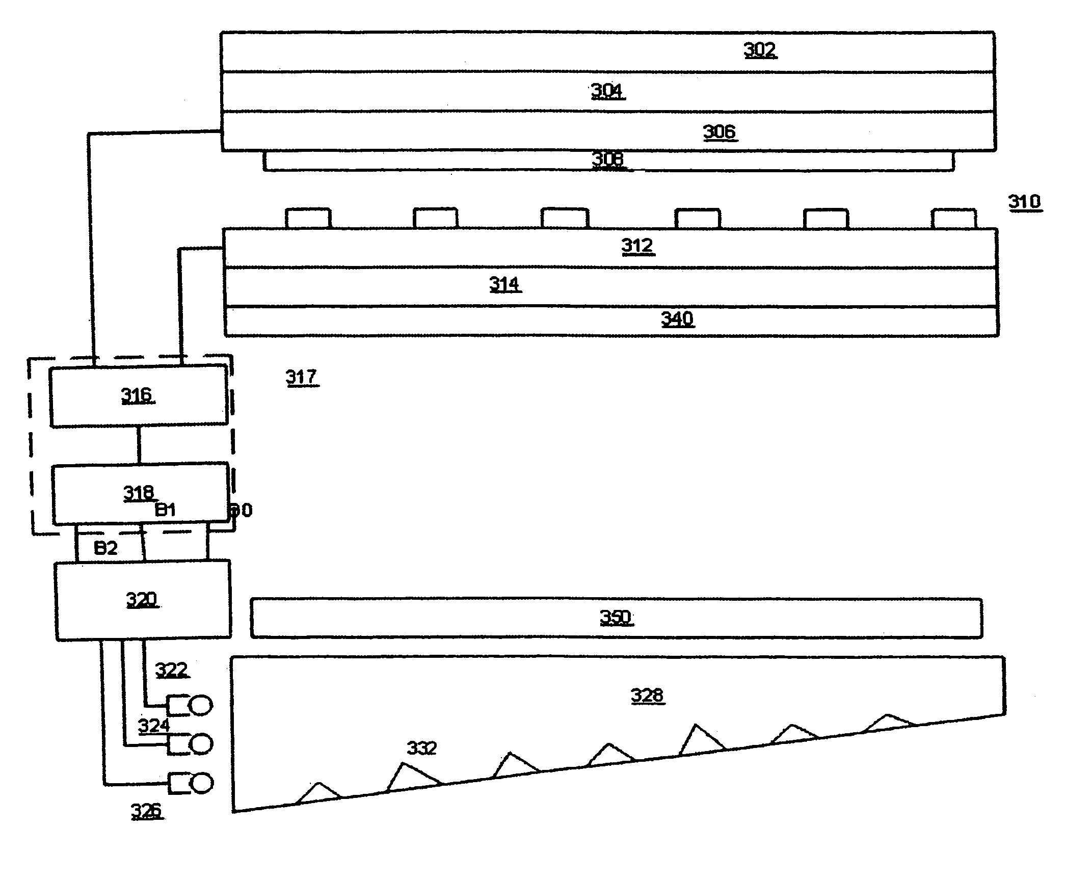
[0013]The present invention relates to a method and apparatus, especially a mobile station such as a handheld communications device, that eliminates bright spots (or hot spots) in the light output pattern from a light guide that illuminates a display. Preferably, the light guide is illuminated by a light source that includes one or more light emitting diodes (LEDs). The LEDs of the light source preferably will include red, green, and blue colours. Other colour schemes, such as cyan, magenta, and yellow, are contemplated by the present invention. Although the present invention is directed to a liquid crystal display per se, the preferred use of the LCD is in a mobile station, such as a wireless portable handheld communications device. Cell phones and pagers are amongst the many handheld devices contemplated by the present invention. Aside from illuminating a display, the method may be used to illuminate a keypad or keyboard, such as a keypad found on a mobile station, or other illumi...


PUM

PropertyMeasurementUnit
transparentaaaaaaaaaa
areaaaaaaaaaaa
sizeaaaaaaaaaa

Abstract

A hot spot filter for a light guide is created by taking an image of the light output pattern of an illuminated light guide. The hot spot filter may be a film, a layer, or an additional liquid crystal display dedicated to attenuating bright spots from the light guide. The hot spot filter may be incorporated into the image display by adjusting the grey scale of individual pixels to provide sufficient compensation.

Description

FIELD OF THE INVENTION[0001]The present invention relates to the field of liquid crystal displays and, particularly, to the field of backlighting for liquid crystal displays and / or keypads.BACKGROUND OF THE INVENTION[0002]Liquid crystal displays are often illuminated by a backlight. When developing an LCD or keypad lighting system, many challenges are encountered that limit the ability to provide a uniformly lit light source to the display or keypad. For example, constraints on the x, y, and z size of the backlight system require tradeoffs or compromises in achieving proper and sufficient optical performance. Especially in those cases where there is little space in the x or y directions (the planar extensions of the light guide), the light guide providing light to the display from a light source (e.g., light emitting diodes—LEDs) or a light source directly illuminating a display may illuminate areas of the display (or keypad) more strongly than other areas. The more strongly lit are...

Claims


Application Information

Patent Timeline
Patent Type & Authority Patents(United States)
IPC IPC(8): G02B6/26G02F1/035G02F1/135
CPCG01J1/04G01J1/26G01J1/4228G02B6/0033G02B6/005G02F1/133611G09G3/3406G09G3/3611H04M1/22G01J1/0418Y10S385/901G02B6/0061G02B6/0068G02B6/0073G02F1/133615G02F2001/133601G09G3/3413G09G3/3426G09G3/3607G09G2310/0235G09G2320/0233G09G2320/0285G09G2320/0646G02F1/133601
Inventor ROBINSON, JAMESDRADER, MARCPURDY, MICHAEL
Owner MALIKIE INNOVATIONS LTD
Learn More