

Image forming apparatus capable of accomplishing uniformity in glossiness
a technology of glossiness and forming apparatus, which is applied in the direction of electrographic process apparatus, instruments, optics, etc., can solve the problems of difficult to reliably form dots of a small size on recording media, low color density, and low color density, and achieves limited toner transferable from image bearing members onto recording media
- Summary
- Abstract
- Description
- Claims
- Application Information
AI Technical Summary
Benefits of technology
Problems solved by technology
Method used
Image

Examples
embodiment 1
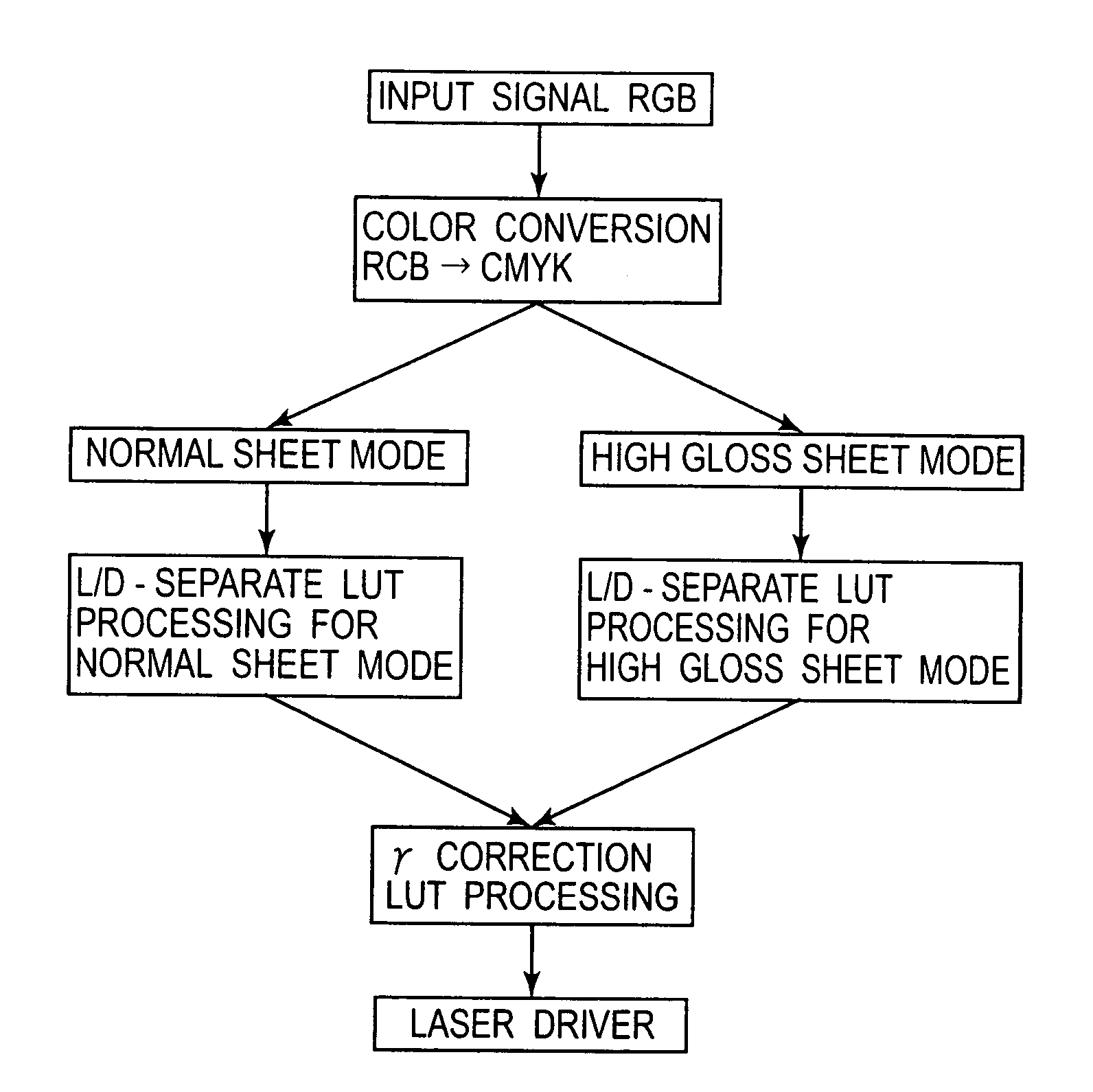
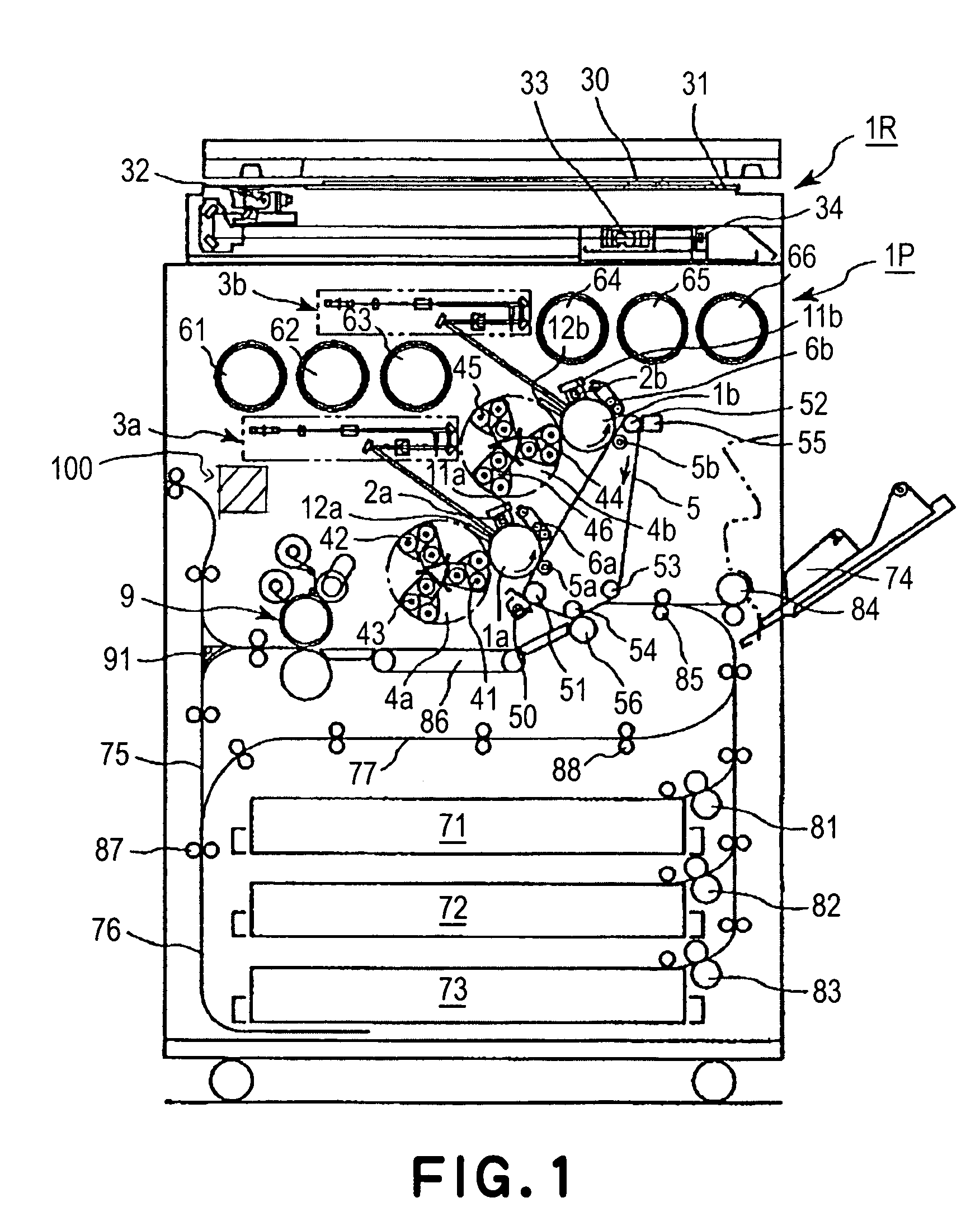
[0042]FIG. 1 is a schematic sectional view of the electrophotographic full-color image forming apparatus in the first embodiment of the present invention, showing the general structure thereof. The full-color image forming apparatus in this embodiment comprises a digital color image reader 1R, which is located in the top portion of the apparatus, and a digital color image printing station 1P, which is in the bottom portion of the apparatus.
[0043]The image forming operation of this apparatus is as follows. That is, an original 30 is placed on the original placement glass platen 31 of the reader portion 1R, and the original 30 is scanned by an exposure lamp 32 so that the light reflected by the original 30 is focused onto the full-color CCD sensor 34 by a lens 33. As a result, video signals representing color components of the original 30 are obtained. These video signals are amplified by an unshown amplification circuit, and then, are sent to an unshown video processing unit, in whic...
embodiment 2
[0080]Not only is the glossiness of a toner image on a recording medium affected by the amount of the toner used per unit area of the recording medium, but also, the glossiness level of the recording medium itself.
[0081]In particular, when forming a toner image on a recording medium with a high level of glossiness, the effect of the glossiness level of the recording medium upon the glossiness level of the toner image, which will be achieved as the toner image is fixed, is substantial.
[0082]FIG. 6 is a graph showing the relationship between the amount of toner used per unit area of a recording medium, and the glossiness level of the toner image which was achieved as the toner image was fixed. This graph shows that the area greater in the amount of toner used per unit area of the recording medium, and the area smaller in the amount of toner used per unit area of the recording medium, are higher in the glossiness level than the area medium in the amount of toner used per unit area of t...
embodiment 3
[0100]FIG. 14 is a schematic sectional view of the image forming apparatus in the fourth embodiment of the present invention, showing the general structure thereof. The image forming apparatus in this embodiment is of a tandem type having six image bearing members 1a, 1b, 1c, 1d, 1e, and 1f.
[0101]The components, members, portions, etc., of this image forming apparatus, identical in function to those of the image forming apparatus in the first embodiment, will be given the same referential numbers as those given in the first embodiment. Next, the structure of this image forming apparatus will be described.
[0102]Referring to FIG. 14, the image forming apparatus has six developing apparatus, and six photosensitive drums as image bearing members.
[0103]In other words, the image forming apparatus in this embodiment is a full-color image forming apparatus. It comprises a digital color image reader 1R, which is located in the top portion of the apparatus, and a digital color image printing...
PUM
 Abstract
Description
Claims
Application Information