
System for scheduling and monitoring a project

a project and project monitoring technology, applied in the field of scheduling a project, can solve the problems of complex monitoring of the progress of the project, difficult to establish proof, and sometimes subject to litigation, and achieve the effect of reducing the time required to complete the entire project and simplifying the evaluation of the state of the proj

Inactive Publication Date: 2006-09-26
MONTEMAYOR SUSANNE +1
View PDF7 Cites 32 Cited by
  • Summary
  • Abstract
  • Description
  • Claims
  • Application Information

AI Technical Summary

Benefits of technology

[0015]It is a further objective that the schedule list of assignments of resources (manpower) be assigned according to an algorithm that minimizes the time required to complete the project.
[0030]One advantage is that all of the jobs in any one period will start at the beginning of the period and will end at the end of the period. This greatly simplifies evaluation of the state of the project during the period and at the end of the period.
[0031]Another advantage is that a determination of the composition of the workforce during the period is conveniently determined (e.g. how many carpenters, plumbers, etc.) This arrangement also provides a desired result that a body of workman having one skill is conveniently and continuously employed during the next period because one period starts when another period ends.
[0032]Another advantage is that the method minimizes the time required to complete the entire project.
[0054]The interleaved update and schedule bars provide that an examiner can determine at a glance the status of the individual jobs and can reallocate resources on an almost daily basis as required to maintain the schedule.

Problems solved by technology

An important problem in preventing over-runs of expense during projects such as a building project is to monitor the progress of the project and relating the progress to a schedule of events.
Violations of contract agreements are sometimes the subject of litigation.
Establishing proof is often difficult because of the difficulty in establishing the timeliness of events.
Monitoring the progress of a project is often complicated by the fact that the most deeply committed parties in the project cannot be constant overseers because their concerns must be divided among a number of such projects.
Furthermore, investors are not usually experts on reading gant charts.
There are numerous constraints imposed on the process of scheduling time, materials and manpower for completing a project such as a large building project.
One of these constraints is that the project consists of numerous jobs that require a variety of skills for completion.
Another constraint is that many of the start of many jobs of a project depend on the completion of combinations of other jobs.
This greatly complicates the requirement to schedule the right kind of workmen and delivery of material to support the project.

Method used


Image

  • System for scheduling and monitoring a project
  • System for scheduling and monitoring a project
  • System for scheduling and monitoring a project

Examples


Embodiment Construction

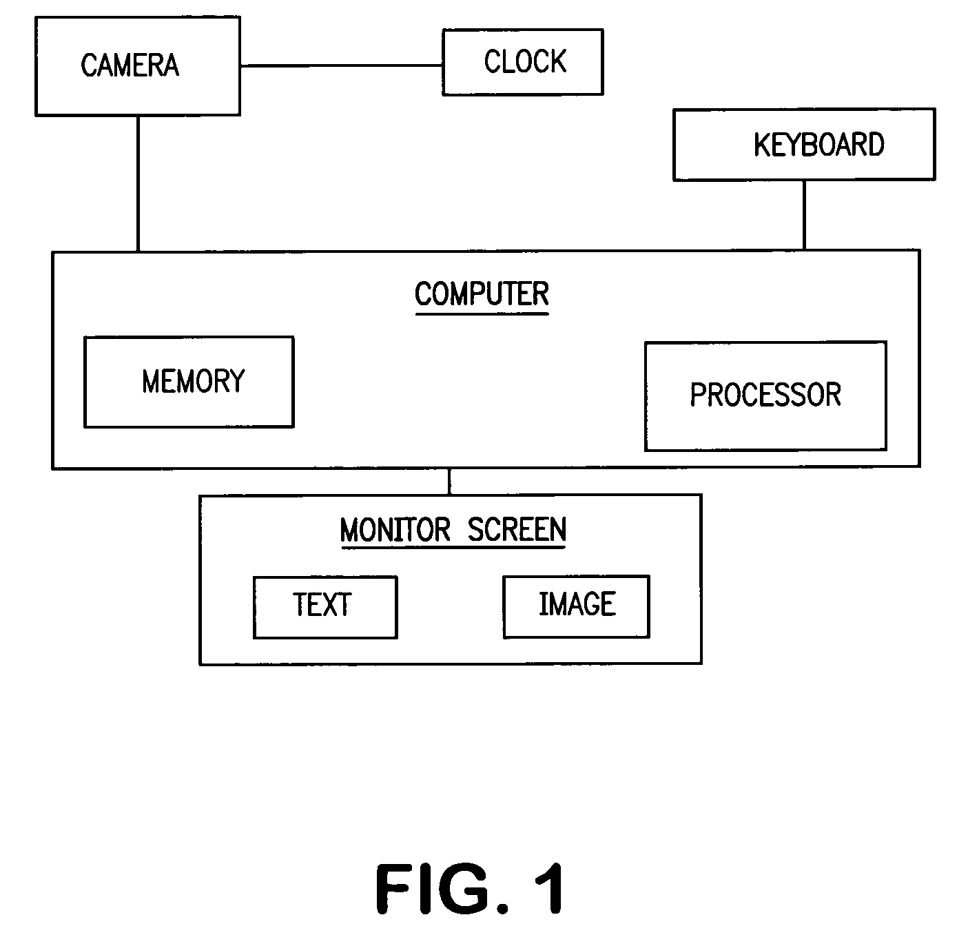
[0073]Turning now to a discussion of the drawings, FIG. 1 shows the system 10 of this invention for documenting progress of a project. There are shown a camera 12, a keyboard 14, a text memory 16, an image memory 18, a processor 20, a clock 22, a monitor screen 24 and a mouse 26 for operating a cursor on the monitor screen 28.

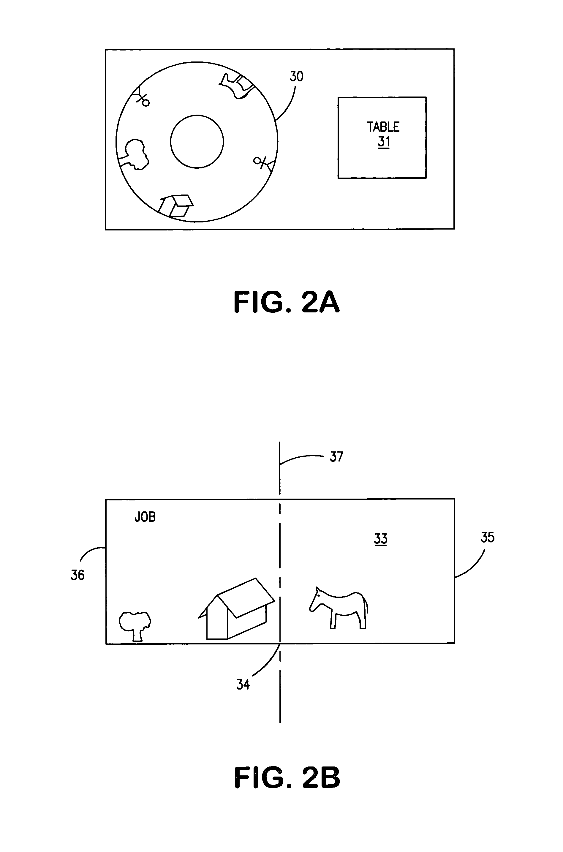
[0074]The camera is preferably a panoramic camera having a 360° field of view. FIGS. 2 A,B, illustrate the formats in presenting the image of the field of view the screen.

[0075]FIG. 2A shows one format, in which the image is a “doughnut”30. The radial direction in the doughnut corresponds to the elevational angle of the field of view and the polar ordinate of the doughnut represents the longitudinal position in the field of view. The table 31 is also shown

[0076]FIG. 2B shows another format, in which the image of the field of view is represented as a rectangular area 33. The horizontal ordinate 34 on the screen 35 represents the longitudinal coordinate in the fi...


PUM


Abstract

A system for managing a project being a plurality of jobs including construction jobs wherein some of the jobs don't require completion of other jobs and remaining jobs require completion of at least one of the independent jobs and / or completion of other jobs in the plurality of jobs. The system separates jobs into lists according to their dependency on other jobs and assigns manpower according to expense, expressed as man days, for completing the job withoin a list period. The system is preferably implemented in conjunction with a panoramic camera and computer. One section of the computer screen displays a 360° field of view of the project. Another section displays a table showing the interrelationship of the jobs. Alpha-numeric indicia, entered by a mouse / keyboard at job locations on the image section of the screen are indexed to jobs scheduled in the table which is entered in the text section of the screen.

Description

CROSS REFERENCE TO PRIOR APPLICATIONS[0001]This application is a non provisional application of provisional application 60 / 560,856 filed Apr. 9, 2004 from which priority is claimedFIELD OF THE INVENTION[0002]This invention relates to scheduling a project and particularly a construction project including time date panoramic photographs to check status.BACKGROUND AND INFORMATION DISCLOSURE[0003]An important problem in preventing over-runs of expense during projects such as a building project is to monitor the progress of the project and relating the progress to a schedule of events. In the case where the project is a building project, such events include ordering and delivery of material, hiring of subcontractors, allowance of easements, payment related to construction status, etc.[0004]Each of these activities are typically the subject of subcontracts whose fulfillment must be completed according to schedule in order that the entire project proceed on time.[0005]Violations of contrac...

Claims


Application Information

Patent Timeline
Patent Type & Authority Patents(United States)
IPC IPC(8): G06Q99/00
CPCG06Q10/06311G06Q10/06
Inventor MONTEMAYOR, SUSANNESMITH, ROBERT SAMUEL
Owner MONTEMAYOR SUSANNE
Learn More