
Image processing system, projector, program, information storage medium and image processing method

a technology of image processing and projector, applied in the field of image processing system, projector, program, information storage medium and image processing method, can solve the problems of image distortion, high labor intensity, and inability to perform stack projection,

Active Publication Date: 2006-10-03
SEIKO EPSON CORP
View PDF13 Cites 30 Cited by
  • Summary
  • Abstract
  • Description
  • Claims
  • Application Information

AI Technical Summary

Benefits of technology

The present invention provides an image processing system, projector, program, information storage medium, and image processing method that can use multiple image projection means to properly overlap and correct distortions of projected images. The system includes sensing means to detect the projected images and their overlap areas, correction information generating means to indicate the positions of the projection areas and the overlap area, and projection area correction means to correct the image signals for the overlap area. The system can also communicate the correction information to other projectors. The technical effect of the invention is to improve the accuracy and quality of image projections in a more efficient and effective manner.

Problems solved by technology

In such an image display, however, the projection angles of the projectors are different from one another and consequently a distortion will occur in an image consisting of the projected and overlapped images.
For such a reason, technical knowledge and great labor are required to perform the stack projection.
For such a reason, it is difficult that the technique of Japanese Patent Application Laid-Open No. 8-168039 causes the projection type display system to properly align the image positions under such a condition that a distortion of an image occurs as when a plurality of projectors are used or when a projector is not opposed directly to a screen.

Method used


Image

  • Image processing system, projector, program, information storage medium and image processing method
  • Image processing system, projector, program, information storage medium and image processing method
  • Image processing system, projector, program, information storage medium and image processing method

Examples


Embodiment Construction

[0112]The present invention will now be described in connection with a plurality of projectors for projecting images overlapped on one another onto a projection target area and with reference to the drawing. By the way, an embodiment shown in the following is not intended to limit the subject matter of the invention as described in the accompanying claims. Moreover, all the components shown in such an embodiment is not necessarily essential for practicing the invention defined by the accompanying claims.

Overall System

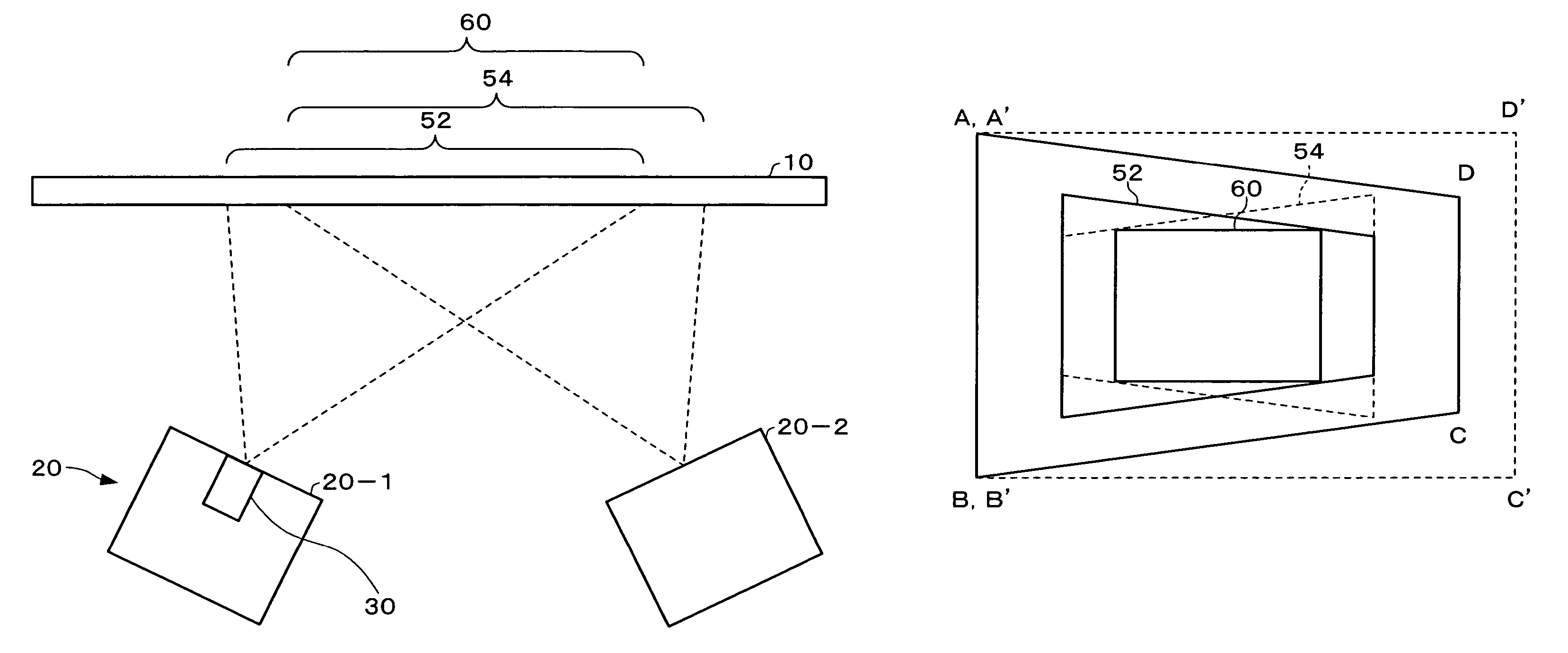
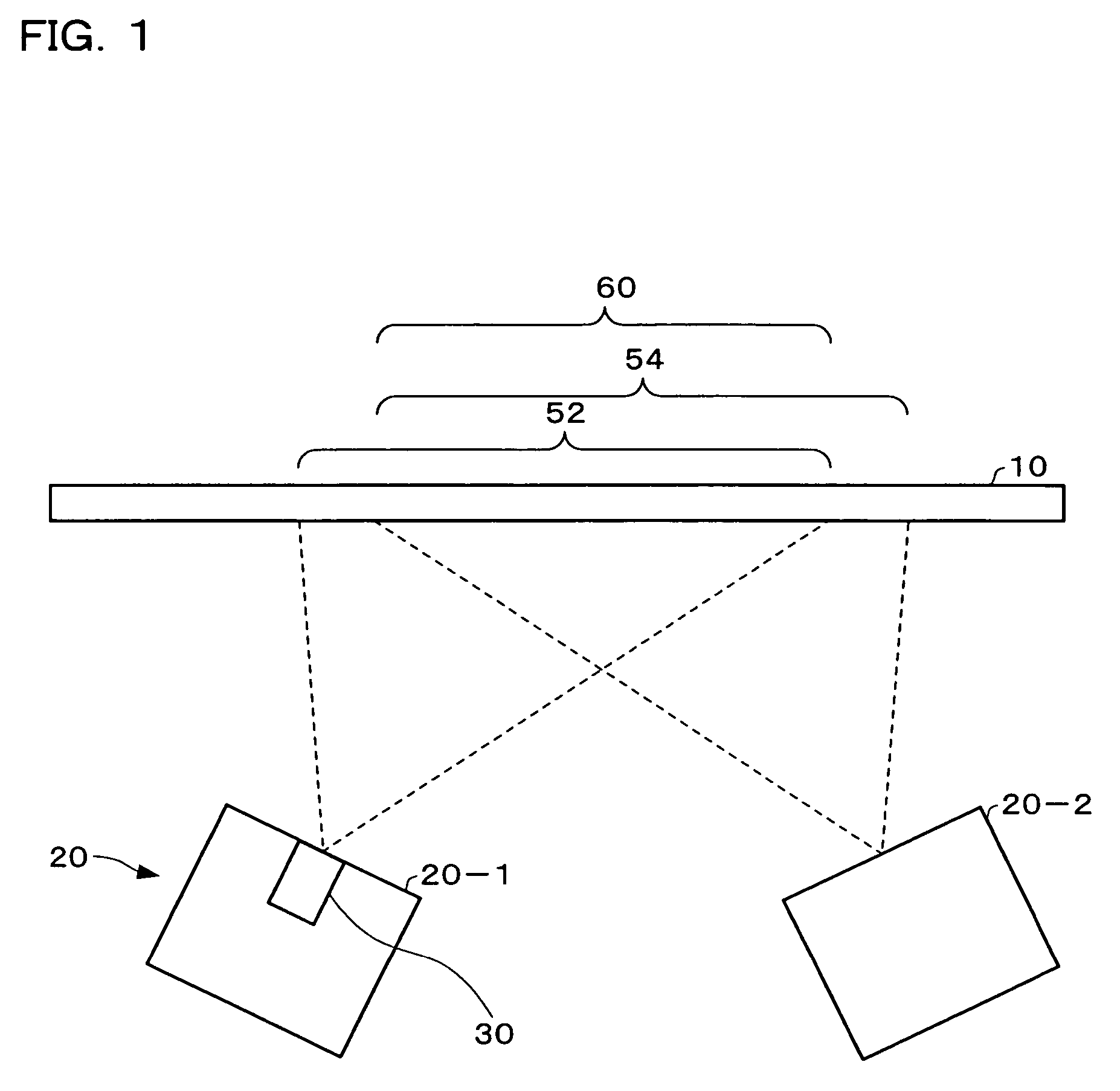
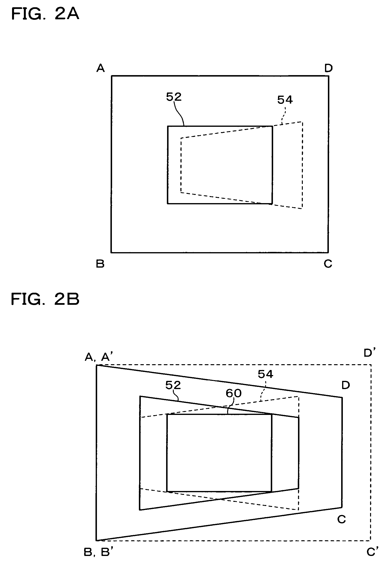
[0113]FIG. 1 schematically shows a state when an image is projected. FIG. 2A schematically shows images 52 and 54 in an sensing region coordinate system while FIG. 2B schematically shows images 52 and 54 in a projection target area coordinate system. FIG. 3A is a schematic view of the image 52 projected by a left-side projector 20-1 while FIG. 3B is a schematic view of the image 54 projected by a right-side projector 20-2.

[0114]The projector 20-1 of this embodiment coop...


PUM


Abstract

To provide an image processing system and the like which can correct image distortions and provide properly overlapped images when a plurality of projectors are used to project overlapped images, a projector includes: an image projection section projecting an image based on image signals to display the image in a manner to overlap another image projected from another projector at a projection target area; sensing section sensing an image and generating sensing information; overlap-area detecting section detecting projection areas for the projection target area, and detecting an overlap area at which the projection areas overlap, based on the sensing information; correction information generating section generating correction information indicating information for positions of the projection areas and a position of the overlap area; and projection area correction section correcting image signals, based on the correction information, to project an image onto a region corresponding to the overlap area.

Description

[0001]Japanese Patent Application No. 2003-126876, filed on May 2, 2003, is hereby incorporated by reference in its entirety.BACKGROUND OF THE INVENTION[0002]The present invention relates to an image processing system, projector, program, information storage medium and image processing method which can correct image signals so that images projected by a plurality of image projection means are overlapped at a projection target area.[0003]To secure the brightness of an image and to improve the dynamic range and color in the image, there has been realized an image display system comprising a plurality of projectors for projecting images so that they could be overlapped one another at a projection target area such as a screen. Such a projection of images is also called “stack projection”.[0004]In such an image display, however, the projection angles of the projectors are different from one another and consequently a distortion will occur in an image consisting of the projected and overl...

Claims


Application Information

Patent Timeline
Patent Type & Authority Patents(United States)
IPC IPC(8): H04N3/22G03B21/14G03B21/00H04N5/74H04N9/31H04N17/00
CPCH04N5/74H04N9/3147H04N9/3197H04N9/3185H04N9/3194H04N9/3182
Inventor WADA, OSAMUKOBAYASHI, MASANOBU
Owner SEIKO EPSON CORP
Learn More