Mounting arrangement for light emitting diodes

a technology of light-emitting diodes and mounting arrangements, which is applied in the direction of chairs, identification means, instruments, etc., can solve the problems of reducing the efficiency and the lifetime of the led, increasing the junction temperature of the led, and the typical inability to maintain a long-term brightness. achieve the effect of high current levels

Inactive Publication Date: 2006-10-03
DIAMOND CREEK CAPITAL LLC
View PDF83 Cites 114 Cited by
  • Summary
  • Abstract
  • Description
  • Claims
  • Application Information

AI Technical Summary

Problems solved by technology

However, a limitation of LEDs is that they typically cannot maintain a long-term brightness that is acceptable for middle to large-scale illumination applications.
However, increased current also increases the junction temperature of the LED.
Increased juncture temperature may reduce the efficiency and the lifetime of the LED.

Method used


Image

  • Mounting arrangement for light emitting diodes
  • Mounting arrangement for light emitting diodes
  • Mounting arrangement for light emitting diodes

Examples


Embodiment Construction

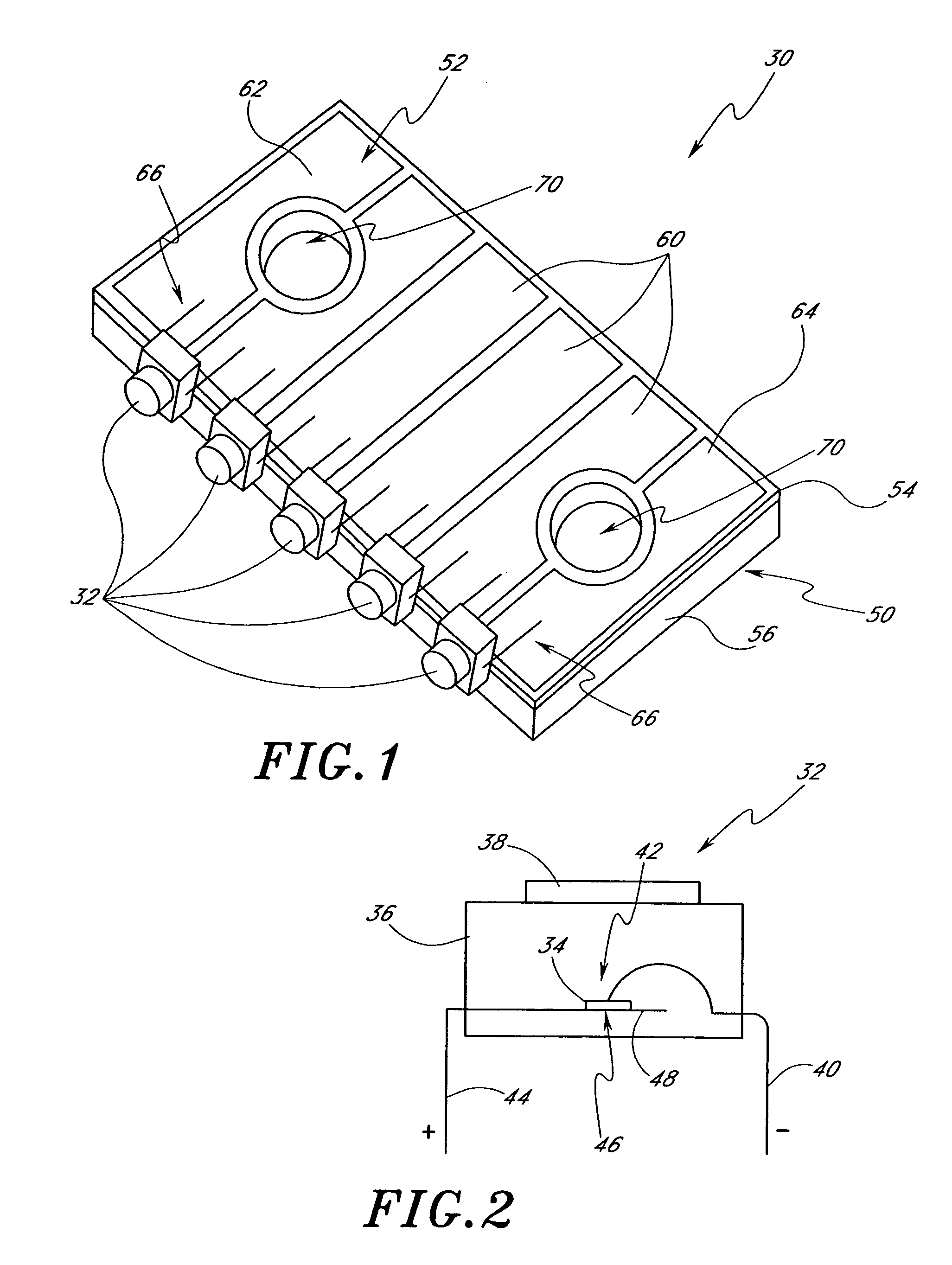
[0041]With reference first to FIG. 1, an embodiment of a light-emitting diode (LED) lighting module 30 is disclosed. In the illustrated embodiment, the LED module 30 includes five pre-packaged LEDs 32 arranged on one side of the module 30. It is to be understood, however, that LED modules having features in accordance with the present invention can be constructed having any number of LEDs 32 mounted in any desired configuration.

[0042]With next reference to FIG. 2, a typical pre-packaged LED 32 includes a diode chip 34 encased within a resin body 36. The body 36 typically has a focusing lens portion 38. A negative lead 40 connects to an anode side 42 of the diode chip 34 and a positive lead 44 connects to a cathode side 46 of the diode chip 34. The positive lead 44 preferably includes a reflector portion 48 to help direct light from the diode 34 to the lens portion 38.

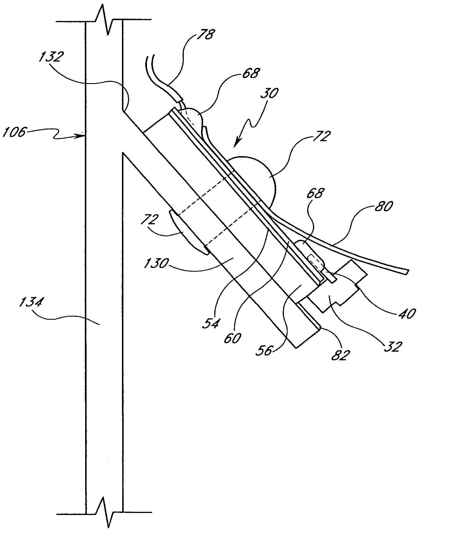
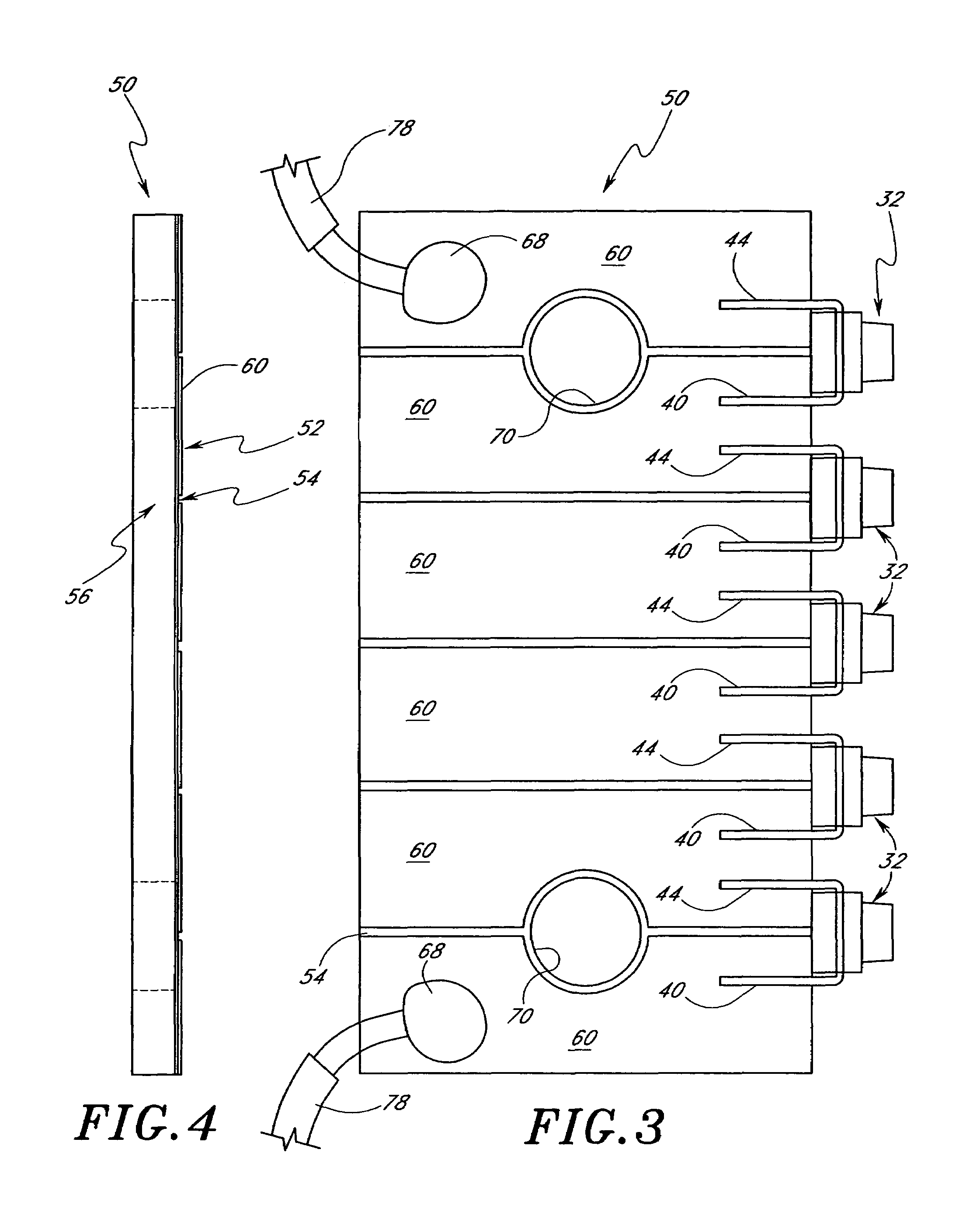
[0043]With next reference to FIGS. 1–5, the LED module 30 preferably comprises the five pre-packaged LED lamps 32 mou...


PUM

PropertyMeasurementUnit
temperatureaaaaaaaaaa
thickaaaaaaaaaa
thickaaaaaaaaaa

Abstract

A modular light emitting diode (LED) mounting configuration is provided including a light source module having a plurality of pre-packaged LEDs arranged in a serial array. The module includes a heat conductive body portion adapted to conduct heat generated by the LEDs to an adjacent heat sink. As a result, the LEDs are able to be operated with a higher current than normally allowed. Thus, brightness and performance of the LEDs is increased without decreasing the life expectancy of the LEDs. The LED modules can be used in a variety of illumination applications employing one or more modules.

Description

RELATED APPLICATIONS[0001]This application is a continuation of copending U.S. application Ser. No. 09 / 693,548, which was filed on Oct. 19, 2000, and which claims priority to U.S. Provisional Patent Application No. 60 / 160,480, which was filed on Oct. 19, 1999 and U.S. Provisional Patent Application No. 60 / 200,531, which was filed on Apr. 27, 2000. The entirety of each of these related applications is hereby incorporated by reference.BACKGROUND OF THE INVENTION[0002]1. Field of the Invention[0003]The present invention is in the field of light emitting diode (LED) lighting devices and more particularly in the field of an LED lighting module having heat transfer properties that improve the efficiency and performance of LEDs.[0004]2. Description of the Related Art[0005]Light emitting diodes (LEDs) are currently used for a variety of applications. The compactness, efficiency and long life of LEDs is particularly desirable and makes LEDs well suited for many applications. However, a limit...

Claims


Application Information

Patent Timeline
Patent Type & Authority Patents(United States)
IPC IPC(8): F21Y101/02H05K1/02H05K3/00
CPCA47C7/725F21V19/001F21V29/004F21V29/2212G09F9/33G09F13/22H05K1/0203F21K9/50F21K9/90F21V15/011H05K3/32F21V29/74F21K9/00Y10T29/49826F21V7/0025F21Y2101/02H05K3/0061H05K2201/10106H05K2201/10446H05K2201/10598Y10S362/80F21V29/70F21K9/60F21V7/005F21V29/507F21V29/89F21Y2103/10F21Y2115/10Y10T29/49133
Inventor POPOVICH, JOHNHONEGGER, GREGORY W.
Owner DIAMOND CREEK CAPITAL LLC
Why Eureka
Try Eureka