Shroud and vane segments having edge notches

a technology of shroud and vane, which is applied in the direction of leakage prevention, motors, light and heating equipment, etc., can solve the problems of difficult circumferential misalignment, and axial mismatch between adjacent shroud segments and adjacent vane segments, so as to improve the control of airflow leakage

Active Publication Date: 2006-10-03
PRATT & WHITNEY CANADA CORP
View PDF14 Cites 31 Cited by
  • Summary
  • Abstract
  • Description
  • Claims
  • Application Information

AI Technical Summary

Benefits of technology

[0005]One object of the present invention is to provide improved control of airflow leakage in a gas turbine engine caused by tolerance stack-up.
[0008]In accordance with a further aspect of the present invention, there is a method provided for controlling an airflow leakage between a shroud assembly and a vane assembly of a gas turbine engine, said leakage being caused by tolerance stack-up of shroud segments and of vane segments of the respective shroud assembly and vane assembly. The method comprises steps of (a) determining a maximum allowable tolerance stake-up of at least one of the shroud segments and the vane segments; and (b) providing a notch in at least one corner of the other one of the shroud segments and the vane segments, the notch being located and sized relative to said maximum allowable tolerance to correspond, when assembled, to any discontinuity due to such tolerance and thereby to inhibit assembly interference which would otherwise be caused by such discontinuity.
[0009]The present invention in one aspect advantageously reduces the randomness of air leakage between the shroud and stator vane assemblies by providing a smaller, and more substantially controllable leakage area. Therefore, the engine performance is improved.

Problems solved by technology

Manufacturing and / or assembly tolerance stack-ups, however, typically results in axial mismatch between adjacent shroud segments and adjacent vane segments and / or circumferential misalignment of the shroud segments with the corresponding vane segments.
However, manufacturing tolerance stack-up typically results in a mismatch between abutting edges 16 of the respective segments 13a, 13b, and sides 20 thus misalign with sides 22 of the segments 11a and 11b.
This results in a gap 18 which allows cooling air flowing through the shroud and vane segments to leak into the gas path, thereby causing inefficiency.
It is difficult to control such airflow leakage when the engine system is designed because the existence and the dimensions of the gap 18 are essentially random (as tolerances intrinsically are).

Method used


Image

  • Shroud and vane segments having edge notches
  • Shroud and vane segments having edge notches
  • Shroud and vane segments having edge notches

Examples


Embodiment Construction

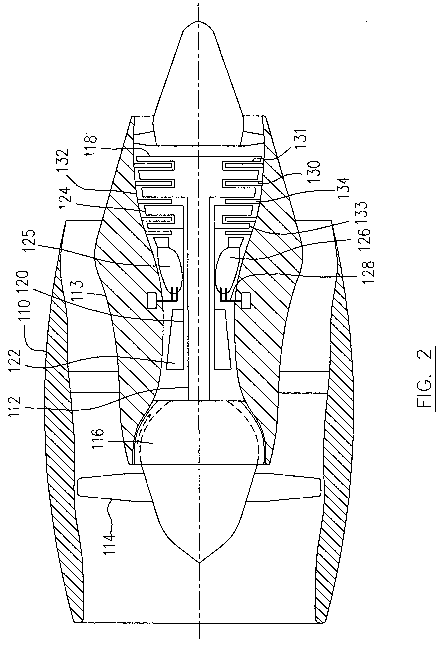
[0021]Referring to FIGS. 2 and 3, a turbofan gas turbine engine incorporates an embodiment of the present invention, presented as an example of the application of the present invention, and includes a housing or a nacelle 110, a core casing 113, a low pressure spool assembly seen generally at 112 which includes a fan 114, low pressure compressor 116 and low pressure turbine 118, and a high pressure spool assembly seen generally at 120 which includes a high pressure compressor 122 and a high pressure turbine 124. There is provided a burner seen generally at 125 which includes an annular combustor 126 and a plurality of fuel injectors 128 for mixing liquid fuel with air and injecting the mixed fuel / air flow into the annular combustor 126 to be ignited for generating combustion gases. The low pressure turbine 118 and high pressure turbine 124 include a plurality of stator vane stages 130 and rotor stages 131. Each of the rotor stages 131 has a plurality of rotor blades 133 encircled by...


PUM


Abstract

Random air flow leakage between a shroud assembly and a stator vane assembly into the gas path of a gas turbine engine due to manufacturing tolerance stack-up is reduced by providing notches to inhibit interference caused by misalignment and / or mismatch of adjacent segments.

Description

FIELD OF THE INVENTION[0001]The present invention relates to a gas turbine engine, and more particularly to reducing the effect of manufacturing or assembly tolerance stack-up between a shroud assembly and an adjacent stator vane assembly.BACKGROUND OF THE INVENTION[0002]A gas turbine engine typically includes a plurality of shroud and stator vane segments in the turbine stages. Manufacturing and / or assembly tolerance stack-ups, however, typically results in axial mismatch between adjacent shroud segments and adjacent vane segments and / or circumferential misalignment of the shroud segments with the corresponding vane segments.[0003]An example of such mismatch or misalignment is illustrated in FIG. 1 which is a schematic top view of turbine shroud segments 11a, 11b and two stator vane segments 13a and 13b. When a sealed connection between the shroud and the stator vane assemblies is required, the abutting edges 15, 16 of the respective shroud and stator vane segments should abut each...

Claims


Application Information

Patent Timeline
Patent Type & Authority Patents(United States)
IPC IPC(8): F01D5/22F01D1/02F01D25/24F01D25/28F02C7/20
CPCF01D9/02F05D2240/11
Inventor SYNNOTT, REMY
Owner PRATT & WHITNEY CANADA CORP
Why Eureka
Try Eureka