Method of repairing a bone joint

a bone joint and bone joint technology, applied in the field of prosthetic members, can solve the problems of affecting the mobility of the spine, affecting the normal movement of the spine, and the screw locking mechanism used with such plates is relatively complicated, so as to achieve normal spine mobility and facilitate the patient's anatomy. the effect of conforming to the patient's anatomy

Inactive Publication Date: 2006-10-03
BONE RUNNER TECH +1
View PDF48 Cites 36 Cited by
  • Summary
  • Abstract
  • Description
  • Claims
  • Application Information

AI Technical Summary

Problems solved by technology

Conventional bone plates, however, are rigid and, thus, significantly inhibit spine mobility.
Additionally, the screw locking mechanisms utilized with such plates are relatively complicated and provide minimal flexibility with respect to fastener positioning, etc.

Method used


Image

  • Method of repairing a bone joint
  • Method of repairing a bone joint
  • Method of repairing a bone joint

Examples


Embodiment Construction

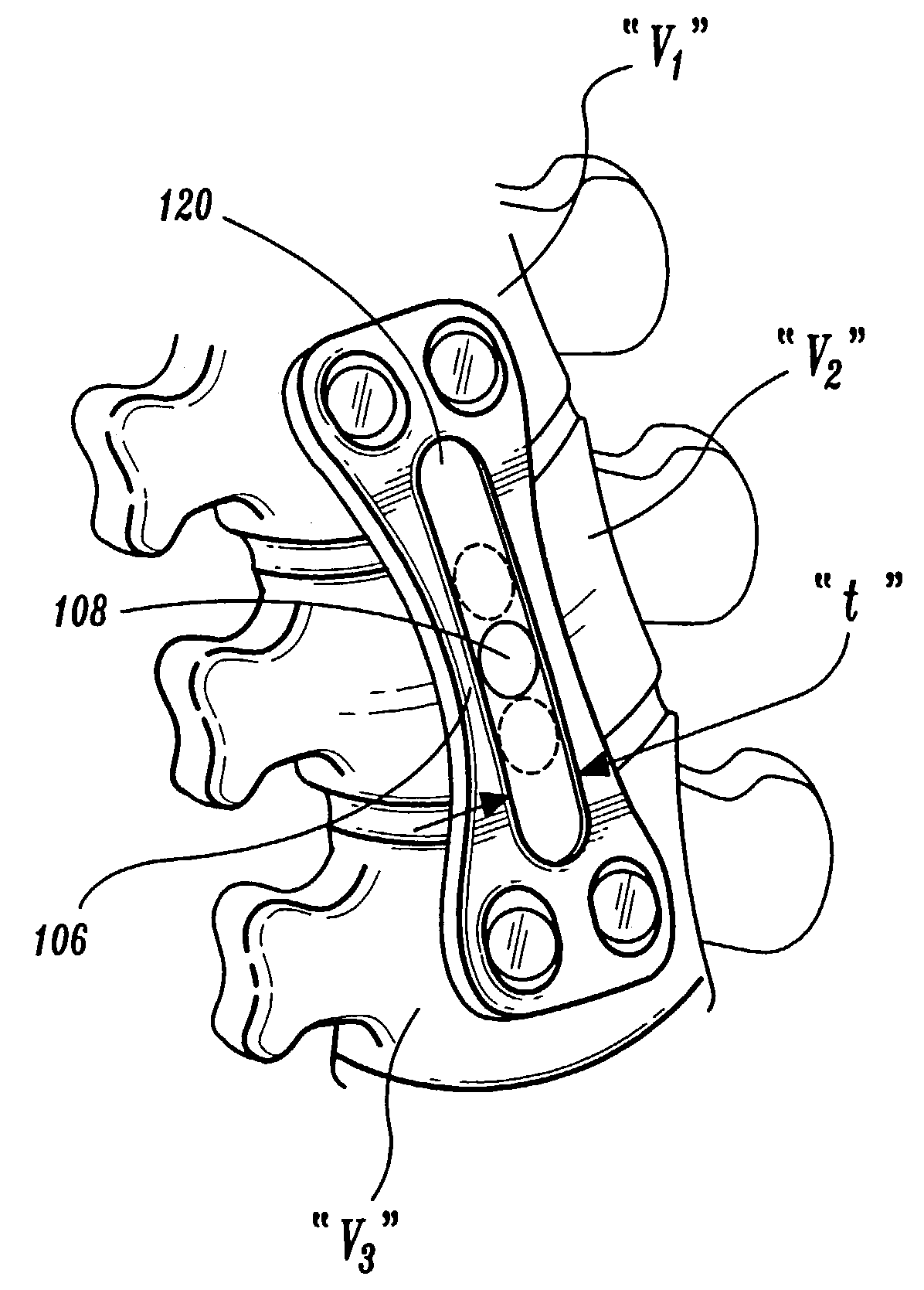
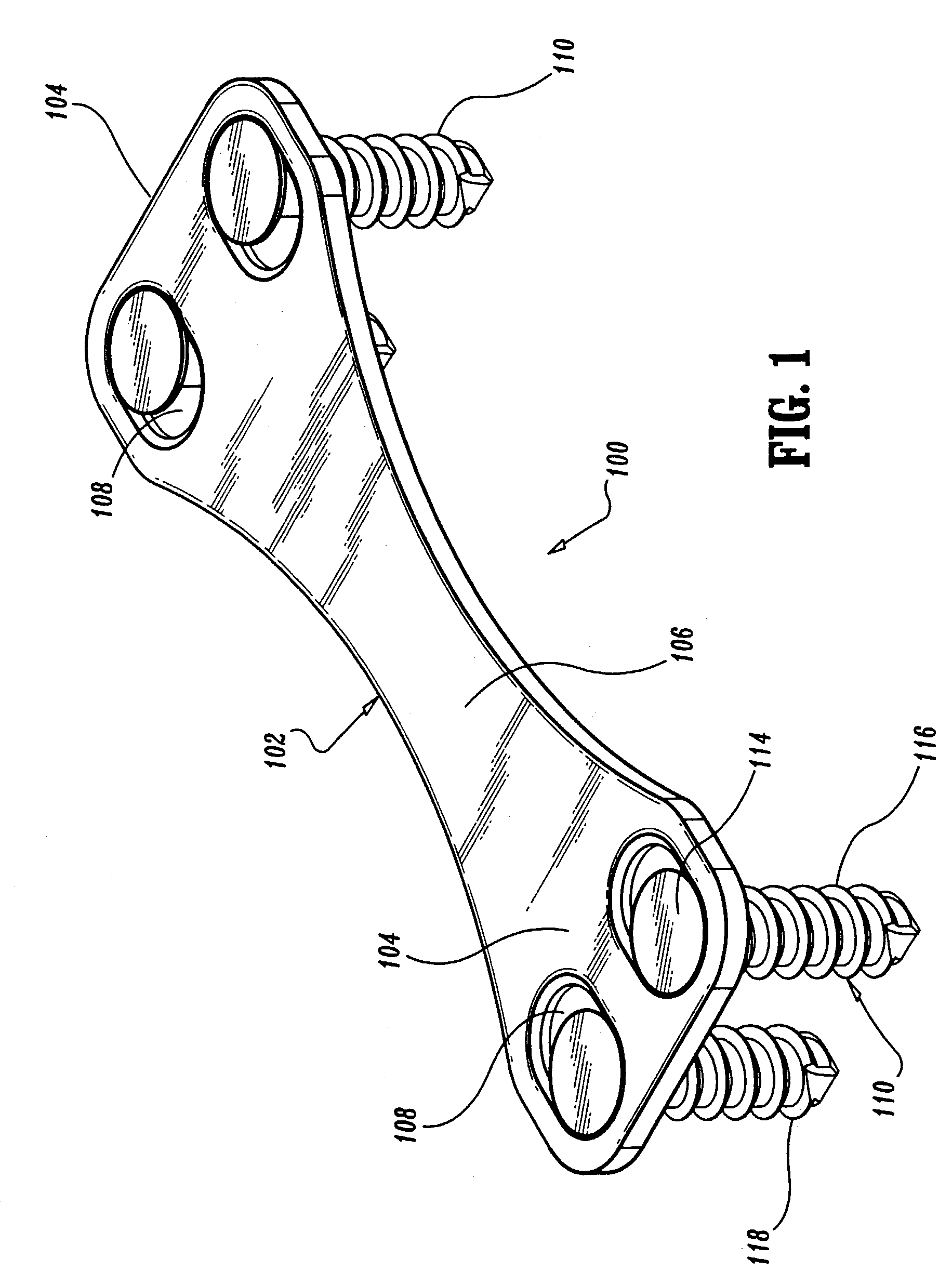
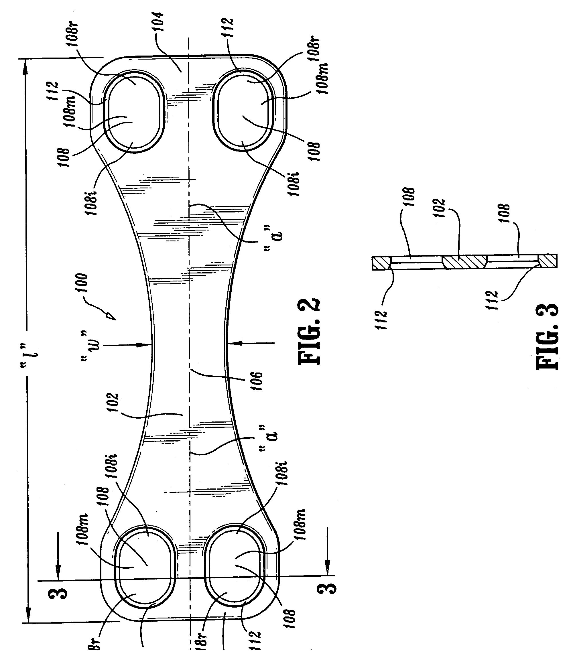
[0014]Referring now to the drawings, in which like reference numerals identify similar or identical elements throughout the several views, there is illustrated the artificial ligament of the present disclosure. The artificial ligament of the present disclosure is intended to replace part or all of the supporting function of a ligament previously removed in connection with a surgical procedure. The artificial ligament has particular application in replacing the supportive function of a spinal ligament, e.g., anterior or posterior, which may have been fully or partially resected during a spinal procedure. The artificial ligament is advantageously dimensioned to be positioned to span adjacent vertebrae to restore the natural biomechanics, e.g., including tensional support and range of motion, of the removed ligament segment. The artificial ligament is contemplated for use with a bone graft, fusion implant or artificial disc to compliment the compressive load characteristics of the impl...


PUM


Abstract

A method of repairing a bone joint by using a simple and flexible artificial ligament which easily conforms to a patient's anatomy and can be used independently or in combination with an intervertebral graft, implant or prosthesis to return stability to the spine subsequent to a surgical spine procedure, is disclosed. The method includes anchoring the artificial ligament to at least two vertebrae to aid in restoring stability to the compromised joint. The artificial ligament is also disclosed.

Description

CROSS-REFERENCE TO RELATED APPLICATIONS[0001]This application is a divisional of U.S. patent application Ser. No. 09 / 543,288 filed Apr. 5, 2000 now U.S. Pat. No. 6,585,769 which claims the benefit of U.S. Provisional Patent Application No. 60 / 127,735, filed Apr. 5, 1999, the entire disclosure of which is hereby incorporated by reference.BACKGROUND OF THE INVENTION[0002]The present disclosure relates generally to prosthetic members for joining or repairing bone segments, including artificial ligaments and, more specifically, to an artificial ligament intended for partial or full replacement of the anterior longitudinal ligament of the anterior lumbar, thoracic or cervical spine.[0003]Ligaments extend between adjacent bone structures and serve a primary function of maintaining and providing appropriate stability to the bone structures to maintain the structures in aligned, spaced relation, particularly when subjected to loads in tension or upon torsional movement. Spinal ligaments sta...

Claims


Application Information

Patent Timeline
Patent Type & Authority Patents(United States)
IPC IPC(8): A61F2/08A61B17/56A61B17/58A61B17/70A61B17/86A61F2/00A61F2/44
CPCA61B17/7059A61F2/08A61F2/0811A61F2002/087A61F2002/0888A61F2002/3013A61F2230/001A61B17/86A61F2/44A61F2/442A61F2/4455A61F2002/0829
Inventor MUHANNA, NABIL L.MIDDLETON, LANCE
Owner BONE RUNNER TECH
Why Eureka
Try Eureka