Multibeam klystron

a multi-beam klystron and beam technology, applied in the field of multi-beam klystrons, can solve the problems that the magnetic focusing would not be suitable for the glass envelope environment, either inside or outside the envelope, and achieve the effects of reducing the weight, size and cost of complicated magnetic structures, accurate focusing, and enhancing efficiency and bandwidth

Inactive Publication Date: 2006-10-03
VANCIL BERNARD K +1
View PDF10 Cites 15 Cited by
  • Summary
  • Abstract
  • Description
  • Claims
  • Application Information

AI Technical Summary

Benefits of technology

[0007]In accordance with one aspect of the present invention, a multibeam klystron is electrostatically focused, eliminating the weight, size, and costs of complicated magnetic structures. The plurality of beams can be accurately focused leading to enhanced efficiency and bandwidth.
[0010]In accordance with another aspect of the present invention, the intermediate construction of the klystron suitably comprises a plurality of metal disk members stacked in immediately adjacent relation, separated only by a thin layer of insulating material, desirably Kapton. Certain of the disk members are recessed to form toroidal cavities. The entire disk stack is easily accommodated and supported from glass rods extending longitudinally within the aforementioned glass envelope.
[0012]It is another object of the present invention to provide a klystron suitable for high power operation which is light in weight and small in overall size.
[0013]It is another object of the present invention to provide a klystron that is economical to manufacture.

Problems solved by technology

This construction is an improvement over the heavy construction heretofore employed in magnetic focusing, and moreover, the magnetic focusing would not be suitable for a glass envelope environment, either inside or outside the envelope.

Method used


Image

  • Multibeam klystron
  • Multibeam klystron
  • Multibeam klystron

Examples


Embodiment Construction

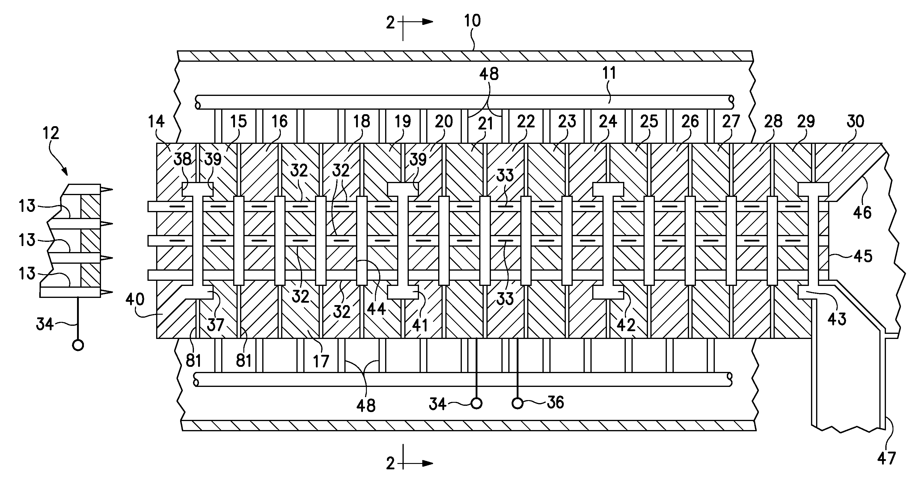
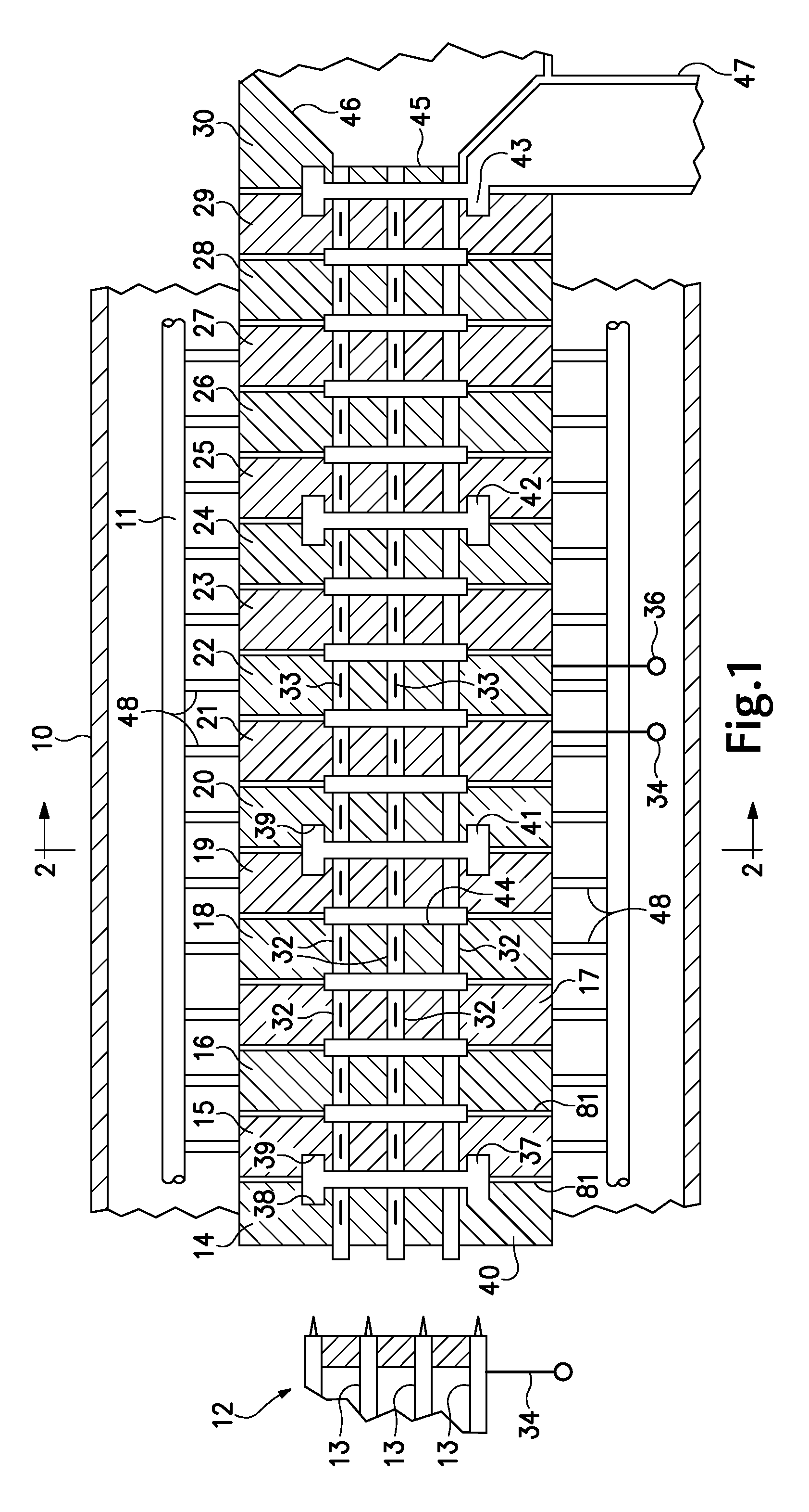
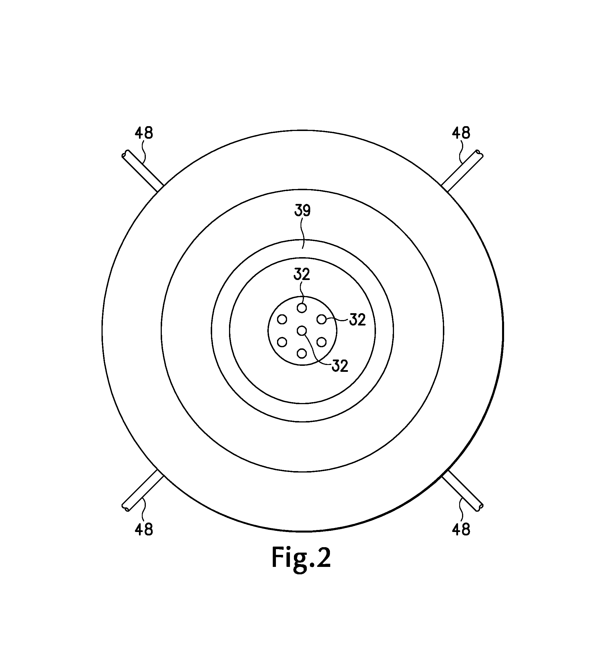
[0019]Referring to the drawings, and particularly to FIGS. 1 and 2, the klystron according to the present invention comprises a glass envelope 10 in which are disposed a plurality of longitudinally extending glass rods 11 upon which the remainder of the structure is supported. Although glass is preferred for the rods and envelope, other insulating material such as a ceramic can be substituted. The envelope construction suitable for embodiments of the invention is further seen in FIGS. 3 and 4. At one end of the envelope is located a cathode structure 12 including, in the specific embodiment, a plurality of small Pierce cathodes 13, here seven in number, that are symmetrically arranged with one center cathode and a group of six symmetrically surrounding and in the same plane with the first. Apertured disk member 14 in FIG. 1 provides an anode electrode having apertures or tunnels parallel with the disk axis and positioned for receiving electron beams 33 produced by cathodes 13. In th...


PUM


Abstract

A multibeam, electrostatically focused klystron includes a plurality of conductive members, ones of which are recessed to provide input and output sections of microwave cavities, wherein focusing voltage is applied between those sections. The conductive members are either spaced along the path of multiple beams, or stacked in insulated relation, in either case being supported by glass rods within a glass envelope.

Description

[0001]This invention was made with Government support under NASA contract. The Government has certain rights in this invention.BACKGROUND OF THE INVENTION[0002]The present invention relates to a multibeam klystron and particularly to a multibeam klystron exhibiting a high bandwidth and substantial power output at high frequencies.[0003]Klystrons can be used both as amplifiers of microwave energy and as oscillators. They consist of three elements: an electron gun which generates a pencil-like flow of electrons accelerated to high energy, a microwave interaction region where the energy in the electron beam is converted to microwave energy, and finally a collector to collect the spent electrons and recover energy that remains. In the aforementioned interaction region the electron beam passes through the center of an r.f. excited toroidal cavity employed for the purpose of accelerating and decelerating electrons in the electron beam at the rate of the r.f. energy in the cavity. The elec...

Claims


Application Information

Patent Timeline
Patent Type & Authority Patents(United States)
IPC IPC(8): H01J25/00H01J25/14
CPCH01J25/14
Inventor VANCIL, BERNARD K.WINTUCKY, EDWIN G.
Owner VANCIL BERNARD K
Why Eureka
Try Eureka