
Power tool and motor controller

a technology of motor controller and power tool, which is applied in the direction of dynamo-electric converter control, dc motor rotation control, instruments, etc., can solve the problems of nozzle fouling, additional clean up time, and at least one deficiency

Inactive Publication Date: 2006-10-03
MILWAUKEE ELECTRIC TOOL CORP
View PDF13 Cites 44 Cited by
  • Summary
  • Abstract
  • Description
  • Claims
  • Application Information

AI Technical Summary

Benefits of technology

The automatic reversal of the motor direction effectively stops the forward movement of the plunger, reducing material waste and cleanup time by preventing after-flow.

Problems solved by technology

While present dispensing guns are functional, they suffer from at least one deficiency.
After-flow (or oozing at the dispensing tip) leads to waste of material, nozzle fouling, dropped material, and additional clean up time.

Method used


Image

  • Power tool and motor controller
  • Power tool and motor controller
  • Power tool and motor controller

Examples


Embodiment Construction

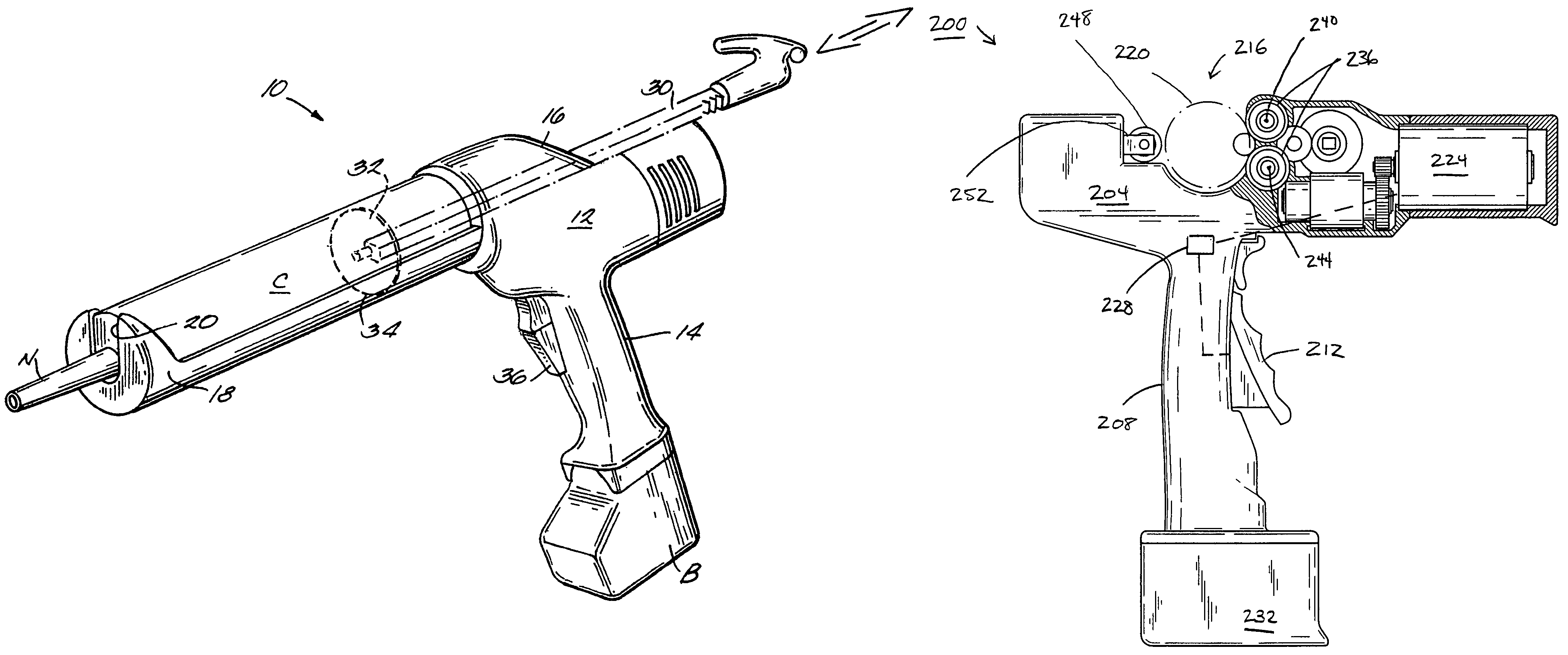
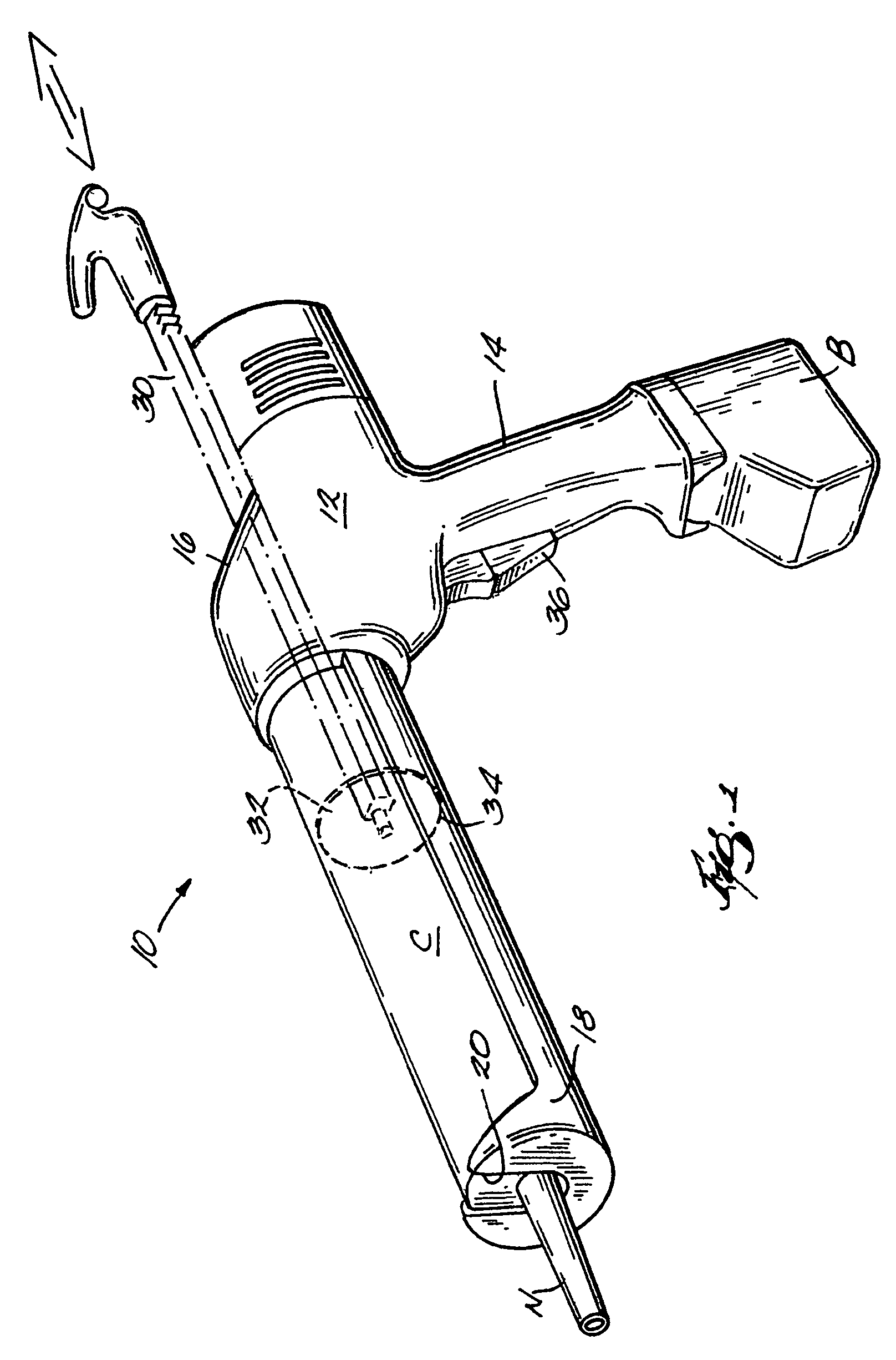
[0026]Before any embodiments of the invention are explained in detail, it is to be understood that the invention is not limited in its application to the details of construction and the arrangement of components set forth in the following description or illustrated in the drawings. The invention is capable of other embodiments and of being practiced or of being carried out in various ways. Also, it is to be understood that the phraseology and terminology used herein is for the purpose of description and should not be regarded as limited. The use of “including,”“comprising” or “having” and variations thereof herein is meant to encompass the items listed thereafter and equivalents thereof as well as additional items. The terms “mounted,”“connected” and “coupled” are used broadly and encompass both direct and indirect mounting, connecting and coupling. Further, “connected” and “coupled” are not restricted to physical or mechanical connections or couplings, and can include electrical co...


PUM


Abstract

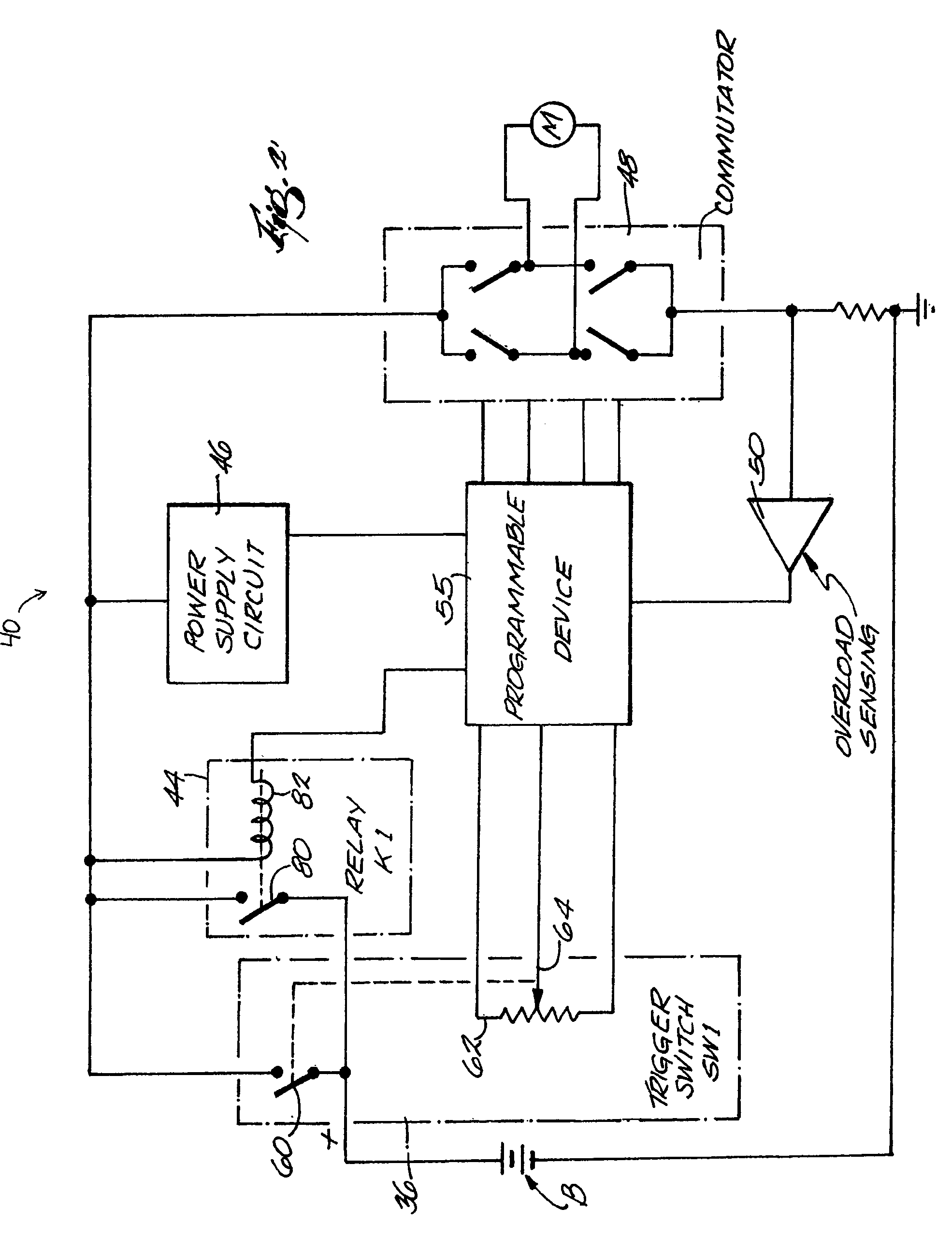
A method and apparatus to automatically reverse the motor of a power tool, such as a dispensing gun or similar tool. In some constructions, a controller automatically reverses the direction of plunger movement and removes the plunger from contact with the back wall of a cartridge. The controller has a trigger switch that is coupled to a power source, such as a battery, and includes a main power on / off switch and a potentiometer. A protection or secondary switch is coupled in parallel to the main power on / off switch. A power supply circuit and a commutator are each coupled to the main and secondary switches. An overload sensor is coupled to the commutator. The controller includes a programmable device that is coupled to the power supply circuit, the potentiometer, the commutator, and the overload sensor. The programmable device is operable to sense actuation and deactuation of the main power on / off switch, read an electromotive force from the potentiometer, and, upon sensing deactuation of the main switch, send a control signal to the commutator to reverse current flow therethrough for a predetermined amount of time, and deactuate the secondary switch when the predetermined time has lapsed.

Description

RELATED APPLICATIONS[0001]This application is a continuation-in-part of U.S. patent application Ser. No. 10 / 152,059, filed May 21, 2002 now U.S. Pat. No. 6,823,134, which is a continuation of U.S. patent application Ser. No. 09 / 731,438, filed Dec. 6, 2000, now U.S. Pat. No. 6,119,903, issued May 21, 2002. The contents of application Ser. No. 10 / 152,059 and of U.S. Pat. No. 6,119,903 are hereby incorporated by reference in their entirety.SUMMARY OF THE INVENTION[0002]The present invention generally relates to methods and devices used to control electric motors. More particularly, the invention relates to methods and apparatus to automatically reverse an electric motor to control the operation of a tool, such as, for example, a dispensing gun, a tube cutter, a saw, etc., driven by the motor.[0003]Hand powered dispensing guns have been available for many years. More recently, pneumatic and electric versions of hand-powered dispensing guns have been made available. Most dispensing guns,...

Claims


Application Information

Patent Timeline
Patent Type & Authority Patents(United States)
IPC IPC(8): H02P1/00B67D7/08B67D7/64H02P7/00
CPCB05C17/00503B05C17/0103B25F5/00G01F11/026H02P7/0044H02P7/29H02H7/0858H02H9/025H02P7/04
Inventor GLASGOW, KEVIN L.CRISP, ROBERT M.
Owner MILWAUKEE ELECTRIC TOOL CORP
Learn More