Imaging device

a technology of imaging device and imaging device, which is applied in the field of imaging device, can solve the problems of large size of imaging device and difficulty in miniaturizing imaging device, and achieve the effect of miniaturizing imaging devi

Inactive Publication Date: 2006-10-03
SONY CORP
View PDF2 Cites 26 Cited by
  • Summary
  • Abstract
  • Description
  • Claims
  • Application Information

AI Technical Summary

Benefits of technology

[0031]With this configuration, the distance C between a corner of a leading end portion of the lens of each camera and a light beam passing through an end, closest to the corner of the lens, of the field of imaging expressed by an angle of view, and the diagonal length A of the imaging element of the camera are determined to satisfy an equation of 0<C<2A. As a result, in a state that the diagonal length A of the imaging device is determined, the distance C between a corner of a leading end portion of the lens of the camera and a light beam passing through an end, closest to the corner of the lens, of the field of imaging can be made small, to thereby miniaturize the imaging device.

Problems solved by technology

The configuration shown in FIG. 2, however, has a disadvantage that a distance between a light beam passing through a lowermost end of the field of view expressed by an angle of view and a corner of a leading end of each lens 42 becomes negative, and therefore, the “vignetting” by the corner of the leading end of the lens 42 occurs in an image.
This limitation further brings a difficulty in miniaturization of the imaging device.
For this reason, according to the related art imaging device, the distance CL has been not set at a suitable value, with a result that the whole size of the imaging device has become large.

Method used


Image

  • Imaging device
  • Imaging device
  • Imaging device

Examples


embodiment 1

[Embodiment 1]

[0047]A first embodiment of an imaging device of the present invention will be described with reference to FIG. 3.

[0048]FIG. 3 is a schematic sectional view showing a configuration of the first embodiment of the imaging device of the present invention. It is to be noted that the cross-section of the imaging device shown in the figure is taken along a vertical plane passing through a center line of the imaging device.

[0049]Referring to FIG. 3, the imaging device according to this embodiment includes eight plane mirrors 4 disposed into an octagonal pyramid shape, and eight cameras 1 disposed in such a manner as to individually face to the eight plane mirrors 4. In the figure, however, only the two plane mirrors 4 and the two cameras 1 disposed on a vertical plane passing through a center line of the imaging device are shown.

[0050]It is to be noted that the eight plane mirrors 4 are provided in this embodiment; however, the present invention is not limited thereto but may...

embodiment 2

[Embodiment 2]

[0058]A second embodiment of the imaging device of the present invention, which is modified from the first embodiment of the imaging device shown in FIG. 3, will be described with reference to FIG. 4.

[0059]This embodiment has the same configuration as that of the first embodiment, except that lenses forming a front lens group 8 are individually disposed in front of the plurality of plane mirrors 4. Accordingly, the plurality of plane mirrors 4 are individually disposed between the lenses forming the front lens group 8 and the lenses 2 mounted to the camera bodies of the cameras 1, which lenses form a rear lens group 2. That is to say, the plane mirrors 4 are disposed between the two lens groups each of which is composed of the plurality of lenses.

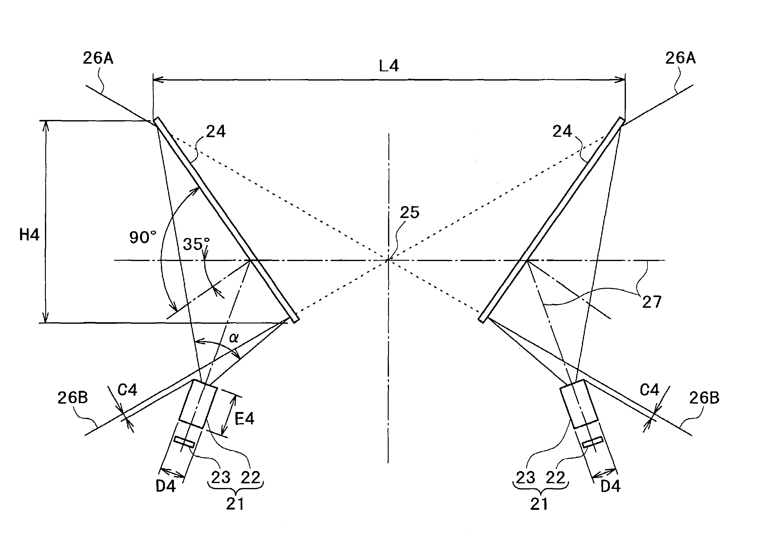
[0060]Even in the imaging device in this embodiment, the incident angle of a light beam traveling along the lens optical axis 7 on each of the plane mirrors 4 is set to 35°.

[0061]With this configuration of the imaging device i...

embodiment 3

[Embodiment 3]

[0077]A third embodiment of the imaging device of the present invention will be described with reference to FIG. 7.

[0078]FIG. 7 is a schematic sectional view showing a configuration of the third embodiment of the imaging device of the present invention.

[0079]Referring to FIG. 7, the imaging device according to this embodiment includes eight plane mirrors 14 disposed into an octagonal pyramid shape, and eight cameras 11 disposed in such a manner as to individually face to the eight plane mirrors 14. In the figure, however, only the two plane mirrors 14 and the two cameras 11 disposed on a vertical plane passing through a center line of the imaging device are shown.

[0080]It is to be noted that the eight plane mirrors 14 are provided in this embodiment; however, the present invention is not limited thereto but may be configured such that a plurality of the plane mirrors 14 may be disposed in a polygonal pyramid shape and the cameras 11 of the same number be disposed in su...


PUM


Abstract

An imaging device includes a plurality of plane mirrors disposed into a polygonal pyramid shape, and a plurality of cameras disposed so as to individually face to the plurality of plane mirrors, wherein each of the plurality of cameras includes a lens, and an incident angle of a light beam traveling along an optical axis of the lens of each of the plurality of cameras on the corresponding one of the plurality of plane mirrors is less than 45°. With this configuration, the sizes of the mirrors and the whole size of the imaging device are reduced, to thereby miniaturize the imaging device.

Description

BACKGROUND OF THE INVENTION[0001]The present invention relates to an imaging device capable of acquiring an image over a wide-angle field, specifically, an image over an omnidirectional or entire circumferential field.[0002]As is well known, there have been developed various camera systems of a type of simultaneously acquiring images over an omnidirectional or entire circumferential field by a number of video cameras contained in one housing.[0003]One of these camera systems has been proposed in U.S. Pat. No. 6,115,176, wherein a plurality of mirrors are disposed into a polygonal pyramid shape in such a manner that centers of view of the mirrors virtually correspond to each other, to thereby eliminate parallax caused among the plurality of cameras.[0004]FIG. 1 is a schematic sectional view showing a configuration of one example of a related art imaging device using a plurality of mirrors disposed into a polygonal pyramid shape as described above.[0005]Referring to FIG. 1, the imagin...

Claims


Application Information

Patent Timeline
Patent Type & Authority Patents(United States)
IPC IPC(8): H04N7/00G02B13/06
CPCG02B13/06
Inventor YOSHIKAWA, KOICHI
Owner SONY CORP
Why Eureka
Try Eureka