Absolute intensity determination for a light source in low level light imaging systems

a technology of light source and absolute intensity, applied in the field of imaging, can solve the problems of imaging data, imaging system not currently available, and different camera designs may affect data output, so as to achieve the effect of assessing the accuracy of the imaging system and its absolute imaging characteristics

Active Publication Date: 2006-10-03
XENOGEN CORP
View PDF34 Cites 29 Cited by
  • Summary
  • Abstract
  • Description
  • Claims
  • Application Information

AI Technical Summary

Benefits of technology

[0012]In another aspect, the present invention relates to systems and methods for calibrating a low-level light imaging system. Techniques described herein employ a light calibration device that is placed within a low level light imaging box to calibrate the system and its constituent imaging components such as the camera, imaging box and lens. The calibration device comprises an array of low-emission light supplies having a known emission. In one embodiment, the array of low-emission light supplies are Lambertian surface emitters with a surface radiance of between about 103 to about 1010 photons / second / centimeter squared / steradian. By taking an exposure of one or more of the low-power light sources, and comparing the processed result with the known emission, the accuracy of the imaging system and its absolute imaging characteristics may be assessed and verified.

Problems solved by technology

In addition, different camera designs may also affect data output.
A problem with using counts as a basis for imaging data analysis is that imaging data may only be analyzed or compared locally within a system, and often under identical imaging conditions.
Such imaging systems are not currently available.

Method used


Image

  • Absolute intensity determination for a light source in low level light imaging systems
  • Absolute intensity determination for a light source in low level light imaging systems
  • Absolute intensity determination for a light source in low level light imaging systems

Examples


Embodiment Construction

[0026]In the following detailed description of the present invention, numerous specific embodiments are set forth in order to provide a thorough understanding of the invention. However, as will be apparent to those skilled in the art, the present invention may be practiced without these specific details or by using alternate elements or processes. In other instances well known processes, components, and designs have not been described in detail so as not to unnecessarily obscure aspects of the present invention.

I. Overview

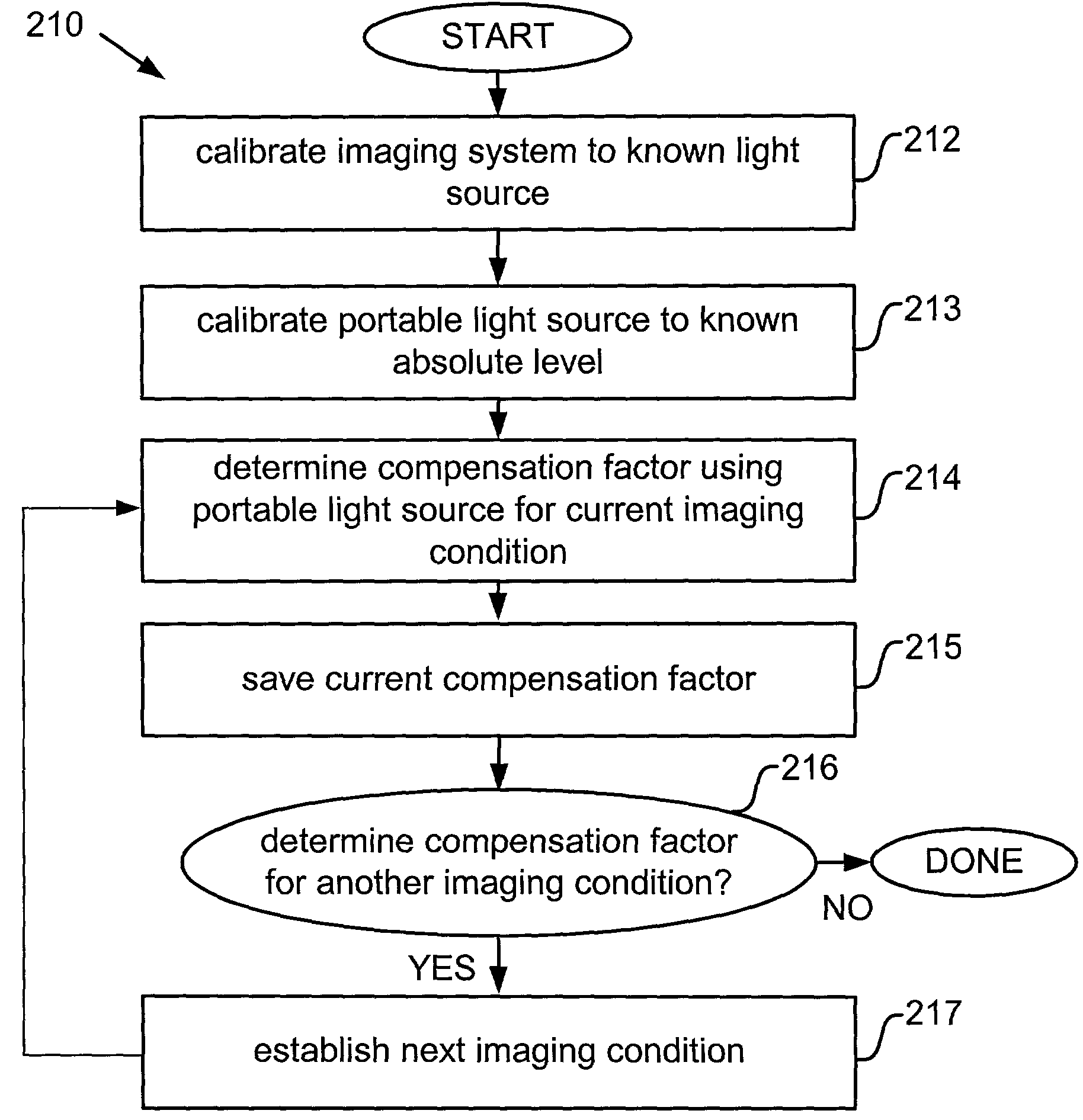
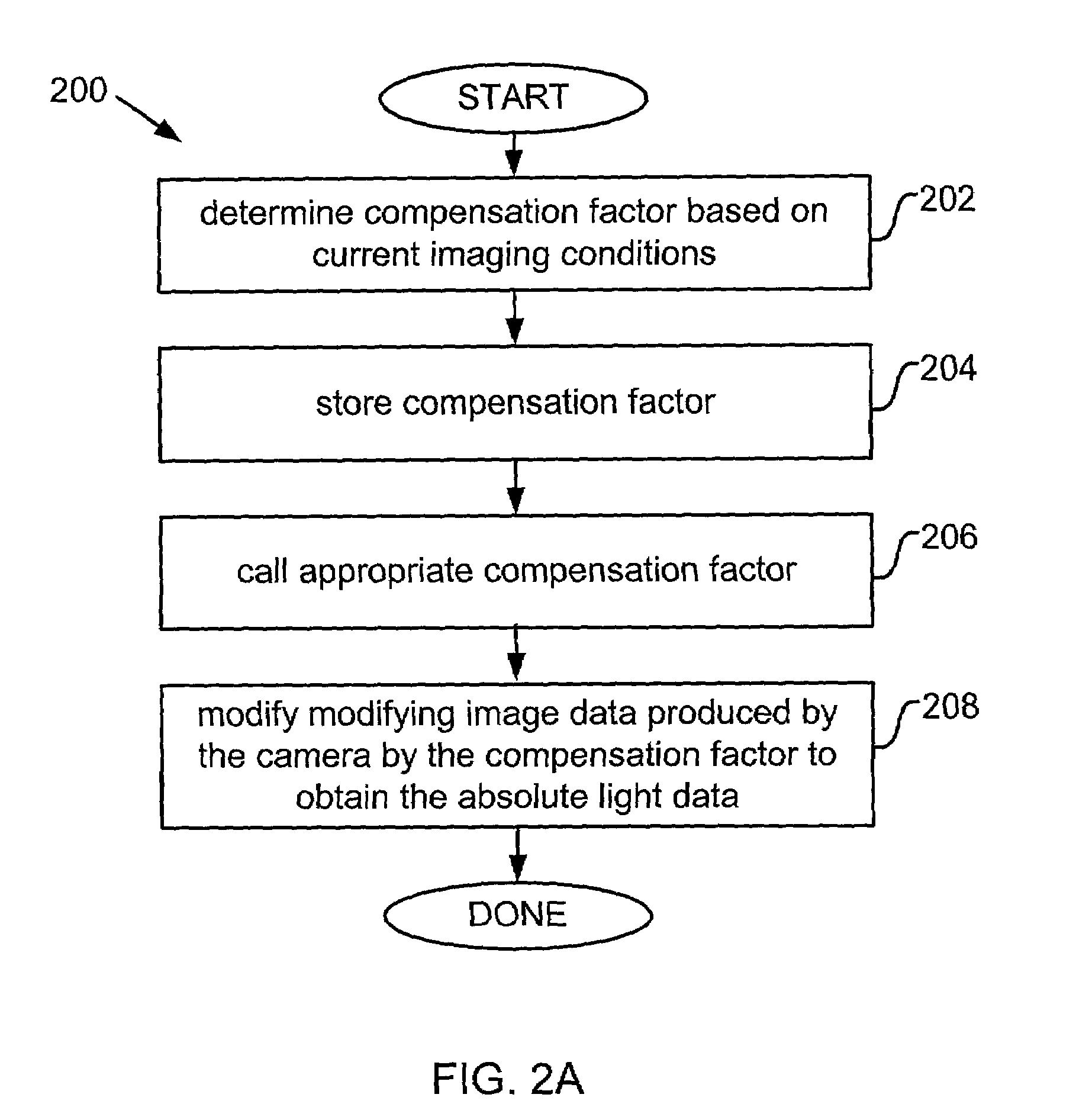
[0027]The present invention converts “relative” units produced by a camera to “absolute” physical units. A distinction between “absolute” physical units and “relative” units as discussed herein is that absolute units refer to light emission data from the source or sample itself, as opposed to counts which refers to light emission incident on a detector—or another relative camera data unit output from a camera component. Regardless of imaging conditions, measurement...


PUM

PropertyMeasurementUnit
solid angleaaaaaaaaaa
constant wavelengthaaaaaaaaaa
light wavelengthaaaaaaaaaa

Abstract

The invention describes systems and methods to obtain and present imaging data in absolute units. The systems and methods convert relative image data produced by a camera to absolute light intensity data using a compensation factor. The compensation factor accommodates for hardware and specific imaging conditions in the imaging system that variably affect camera output. The present invention determines the compensation factor based on assessing the output of the camera against a known light source for a specific set of imaging conditions in the imaging system. The compensation factor is then stored in memory corresponding to the specific set of imaging conditions. Upon subsequent imaging with the set of imaging conditions, the corresponding compensation factor is called from memory and applied to the camera output. A compensation factor may be determined and stored for each hardware state and imaging condition available to the imaging system.

Description

CROSS-REFERENCE TO RELATED APPLICATIONS[0001]This application claims priority under 35 U.S.C. §19(e) from U.S. Provisional Patent Application No. 60 / 299,685 filed on Jun. 20, 2001, which is incorporated by reference for all purposes; this application is also a continuation-in-part of U.S. Patent Application entitled “Light Calibration Device for Use in Low Level Light Imaging Systems” by Michael Bo Nelson et al., filed on Feb. 6, 2002 (U.S. application Ser. No. 10 / 068,573), now U.S. Pat. No. 6,919,919 which is incorporated by reference herein for all purposes.FIELD OF THE INVENTION[0002]The present invention relates generally to imaging. In particular, the present invention relates to systems and methods for obtaining the absolute intensity of a light source which is particularly useful in imaging and research applications.BACKGROUND OF THE INVENTION[0003]One new and specialized type of imaging involves the capture of low intensity light—often on the order of only tens to hundreds o...

Claims


Application Information

Patent Timeline
Patent Type & Authority Patents(United States)
IPC IPC(8): H04N17/00G01J1/00G01J1/08G01N21/27
CPCG01J1/08G01N21/278G01N21/763H04N5/217H04N23/81
Inventor RICE, BRADLEYCABLE, MICHAEL D.
Owner XENOGEN CORP
Why Eureka
Try Eureka