Optical disk device and tilt correction method

a technology of optical disk and tilt correction, which is applied in the direction of digital signal error detection/correction, instruments, recording signal processing, etc., can solve problems such as data recording and reproduction obstacles

Inactive Publication Date: 2006-10-03
RICOH KK
View PDF12 Cites 5 Cited by
  • Summary
  • Abstract
  • Description
  • Claims
  • Application Information

AI Technical Summary

Benefits of technology

[0022]Since the reflectivity in the recorded region is smaller than that in the unrecorded region in general, when traversing from an unrecorded region to a recorded region, or from a recorded region to an unrecorded region, the strength of the reflected laser beam changes greatly, obstructing proper tilt detection. According to the above aspect of the present invention, by shifting the actual measurement position out of the boundary area between the recorded region and the unrecorded region, this problem can be prevented and proper tilt correction can be made.

Problems solved by technology

If the optical axis of the object lens tilts relative to the optical disk, optical aberrations arise at the light spot, and this may present obstacles to data recording and reproduction.
However, in the method of measuring in advance tilt data, which cause the RF signal and the TE signal to become the maximum, at a number of positions, and making tilt corrections based on the measured tilt data, because the magnitude of the tilt and its variation are small in the inner region of the optical disk, and large in the peripheral region of the optical disk, complicated calculations and tilt data of many positions are needed for interpolation to correct tilt between the two regions.

Method used


Image

  • Optical disk device and tilt correction method
  • Optical disk device and tilt correction method
  • Optical disk device and tilt correction method

Examples


first embodiment

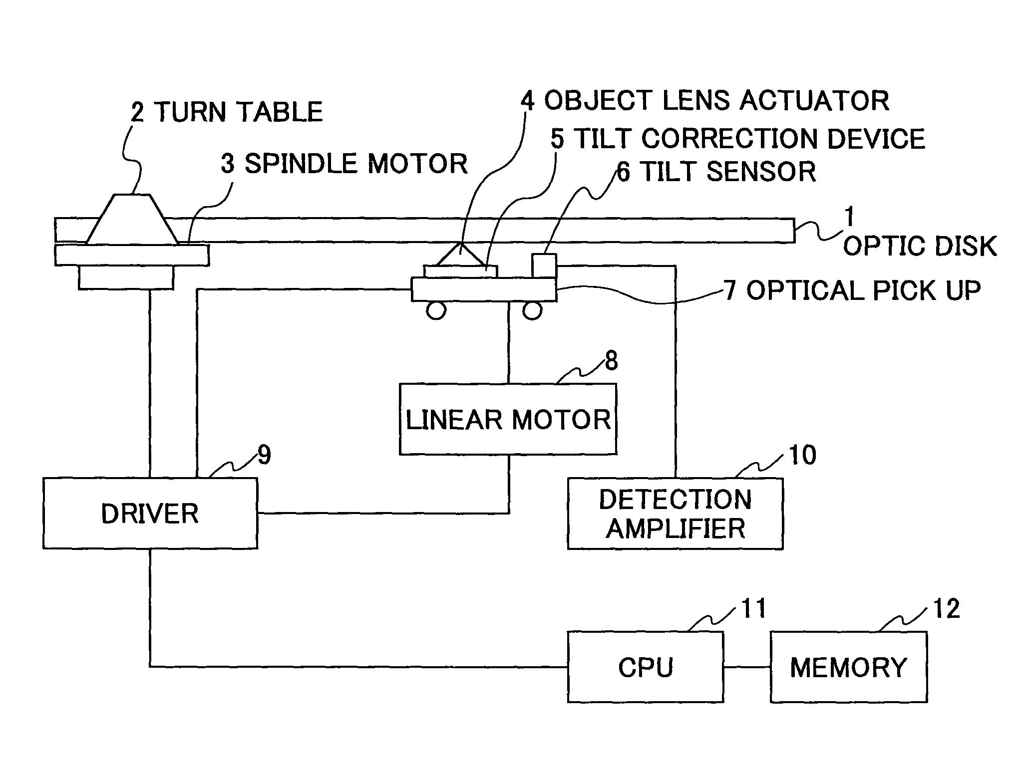
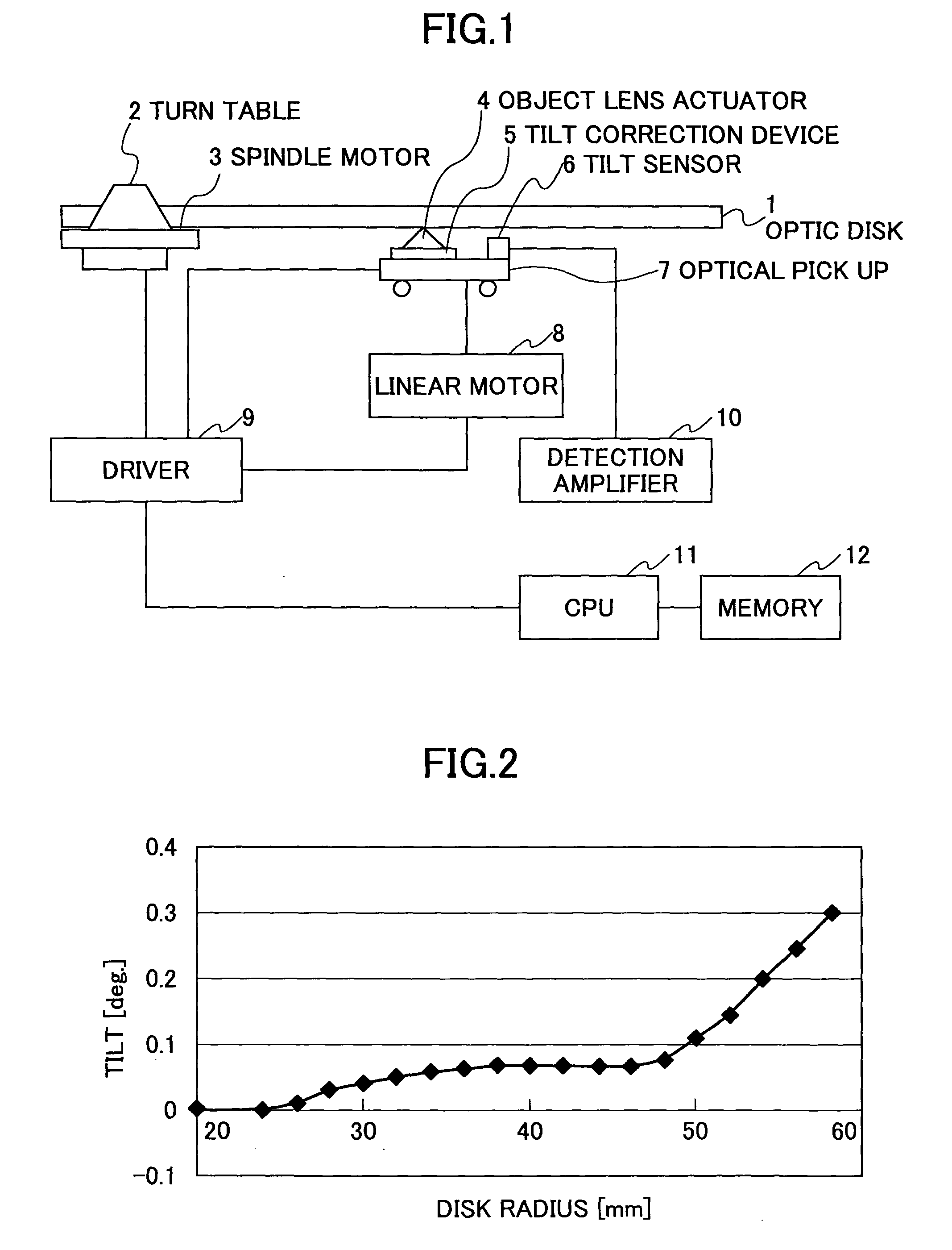
[0033]FIG. 1 is a block diagram showing a schematic configuration of an optical disk device according to the present invention.

[0034]The optical disk device shown in FIG. 1 includes an optical disk 1, a turnable table 2, and a spindle motor 3. The turnable table 2 is attached to the spindle motor 3, and the optical disk 1 on the turnable table 2 is rotated by the spindle motor 3.

[0035]The optical disk device further comprises an optical pickup 7 including an object lens actuator 4, a tilt correction device 5, and a tilt sensor 6. The object lens actuator 4 is attached to the optical pickup 7 with the tilt correction device 5 in between.

[0036]In addition, the optical disk device comprises a linear motor 8 including a step motor for moving the optical pickup 7 in the radial direction, a driver circuit 9 for driving the spindle motor 3, the tilt correction device 5, and the linear motor 8, a detection amplifier 10, a CPU 11, and a memory 12.

[0037]The optical pickup 7 is mounted on a dr...

second embodiment

[0059

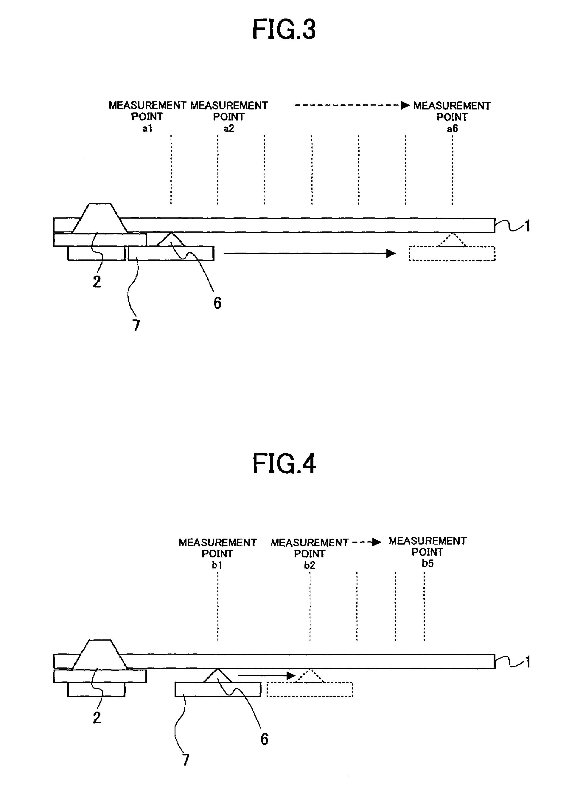
[0060]FIG. 5 is a view showing a correction method according to a second embodiment of the present invention.

[0061]In the first embodiment, the intervals between two adjacent preset measurement positions in the radial direction are set to be shorter and shorter from the inner region to the peripheral region of the optical disk 1. Further, the surface of the optical disk 1 is divided into regions in conjunction with the varying intervals, and tilt correction is performed in each region based on the tilt detection results therein.

[0062]In the present embodiment, for example, the regions between two adjacent preset measurement positions b1 and b2, b2 and b3, b3 and b4, and b4 and b5 are denoted as z1, z2, z3 and z4, respectively, and the mid-points of the regions z1, z2, z3 and z4 are denoted as c1, c2, c3, and c4, respectively. The tilt data at the mid-points c1, c2, c3, and c4 are measured beforehand and stored in the memory 12.

[0063]And then, for example, when making tilt corre...


PUM

PropertyMeasurementUnit
distanceaaaaaaaaaa
incident angleaaaaaaaaaa
track densityaaaaaaaaaa

Abstract

An optical disk device and a tilt correction method capable of high precision tilt correction with a smaller number of measurement positions are provided. Prior to data recording and reproduction, a number of measurement positions are set in the radial direction on an optical disk with intervals between two adjacent measurement positions shorter and shorter from the inner region to the peripheral region of the optical disk. The tilt at each of the measurement positions is measured, and the resulting tilt data are stored in a memory. The tilt data are used for making tilt corrections when recording or reproducing data on the optical disk.

Description

BACKGROUND OF THE INVENTION[0001]1. Field of the Invention[0002]The present invention relates to an optical disk device and a tilt correction method able to correct an incident angle of a laser beam so that the laser beam perpendicularly irradiates the surface of an optical disk.[0003]2. Description of the Related Art[0004]Optical disks, such as CD-ROMs, CD-Rs, and CD-RWs, are widely used. Particularly, in recent years and continuing, DVD type optical disks show up in greater numbers, and have higher track density and thus higher capacity than the above CD type optical disks. The reproduction-only DVD has become wide-spread, and the recordable DVD is being brought into practical use.[0005]To record or reproduce data on an optical disk, an object lens is provided to condense a laser beam to form a small light spot on a track of the optical disk. If the optical axis of the object lens tilts relative to the optical disk, optical aberrations arise at the light spot, and this may present...

Claims


Application Information

Patent Timeline
Patent Type & Authority Patents(United States)
IPC IPC(8): G11B7/00G11B7/007G11B7/085G11B7/09G11B7/095
CPCG11B7/00736G11B7/0945G11B7/0956
Inventor NINOMIYA, MASAKIOHNO, TAKEHIDE
Owner RICOH KK
Why Eureka
Try Eureka