Diagnostic X-ray system

a technology of x-ray system and x-ray loading factor, which is applied in the field of diagnostic x-ray system, can solve the problem of inability to determine the loading factor that can provide optimal brightness, and achieve the effect of reducing the number of x-rays

Inactive Publication Date: 2006-10-03
TOSHIBA MEDICAL SYST CORP
View PDF11 Cites 21 Cited by
  • Summary
  • Abstract
  • Description
  • Claims
  • Application Information

AI Technical Summary

Benefits of technology

[0014]That is to say, one aspect of the invention provides a diagnostic X-ray system, including: an X-ray generating unit that radiates an X-ray to a subject at a predetermined X-ray loading factor; a beam limiting unit that limits a radiation region of the X-ray through beam limiting; an image generating unit that generates an image of a predetermined size based on the X-ray passing through an interior of a body of the subject; a brightness computing unit that computes brightness related to a predetermined region within the image; a controller that determines an X-ray loading factor based on the brightness computed in the brightness computing unit and performs feedback control of the X-ray loading factor with respect to the X-ray generating unit; and a judging unit that judges whether a region corresponding to the beam limiting superposes the predetermined region within the image, wherein when the judging unit judges superposition, the brightness computing unit transforms the predetermined region to a given region that does not superpose the region corresponding to the beam limiting, and computes brightness based on the given region.

Problems solved by technology

This results in brightness control such that brightens the X-ray fluoroscopic image exceedingly, and thereby makes it impossible to determine X-ray loading factors that can provide optimal brightness.

Method used


Image

  • Diagnostic X-ray system
  • Diagnostic X-ray system
  • Diagnostic X-ray system

Examples


Embodiment Construction

[0024]The following description will describe embodiments of the invention with reference to the drawings. The invention is applicable to both a fluoroscopic diagnostic X-ray system and an imaging diagnostic X-ray system (or a diagnostic X-ray system picking up an image in both a fluoroscopic mode and an imaging mode).

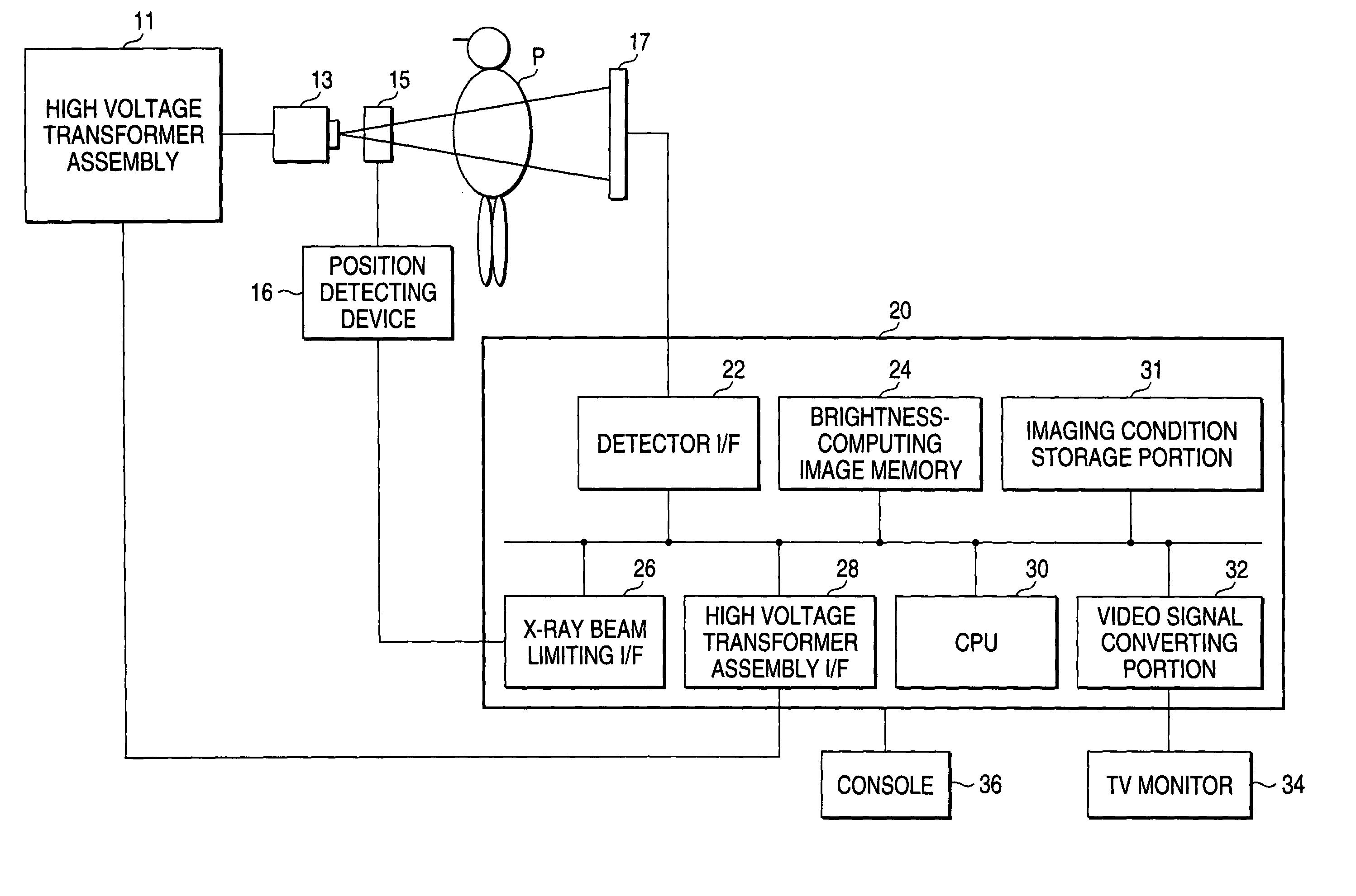
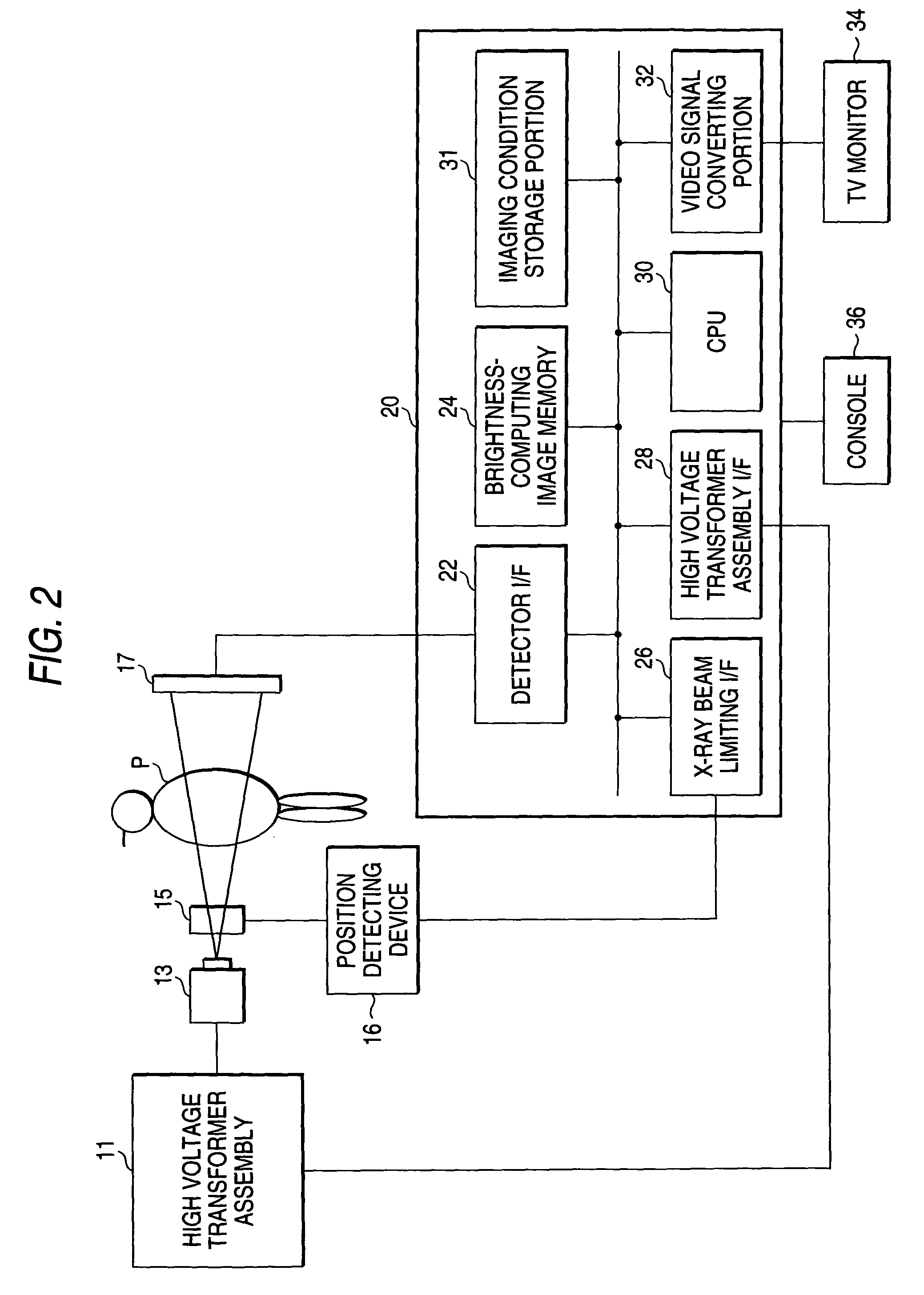
[0025]FIG. 2 is a view schematically showing an arrangement of a diagnostic X-ray system according to this embodiment.

[0026]Referring to FIG. 2, the diagnostic X-ray system comprises a high voltage transformer assembly 11, an X-ray tube 13, an X-ray beam limiting device 15, a detector 17, and a fluoroscopic image processing device 20 provided with a detector interface 22, a brightness-computing image memory 24, an X-ray beam limiting interface 26, a high voltage transformer assembly interface 28, a CPU 30, an imaging condition storage portion 31, and a video signal converting portion 32, as well as a TV monitor 34 and a console 36 both connected to an apparatus main bo...


PUM

PropertyMeasurementUnit
strengthaaaaaaaaaa
brightnessaaaaaaaaaa
sizeaaaaaaaaaa

Abstract

A region affected by X-ray beam limiting within a fluoroscopic image is specified based on position information on beam limiting by an X-ray beam limiting device. A judgment is made as to whether the region affected superposes a first brightness measuring region (region of interest) within the X-ray fluoroscopic image, and when superposition is not judged, automatic brightness control is performed based on the first brightness measuring region. When superposition is judged, the first brightness measuring region is transformed, and automatic brightness control is performed with reference to a second automatic brightness measuring region that does not superpose the region affected.

Description

CROSS-REFERENCE TO RELATED APPLICATIONS[0001]This is a Continuation Application of PCT Application No. PCT / JP02 / 03210, filed Mar. 29, 2002, which was not published under PCT Article 21(2) in English.[0002]This application is based upon and claims the benefit of priority from the prior Japanese Patent Application No. 2001-097116, filed Mar. 29, 2001, the entire contents of which are incorporated herein by reference.BACKGROUND OF THE INVENTION[0003]1. Field of the Invention[0004]The present invention relates to a diagnostic X-ray system with automatic brightness control processing.[0005]2. Description of the Related Art[0006]A diagnostic X-ray system is an imaging apparatus that displays variance in strength of X-rays passing through the interior of a subject as a gray-scale image, and includes various types adapted for specific use in diagnosis, treatment, etc. Means for turning a transmission X-ray image into a visible image is roughly divided into two methods: imaging and fluorosco...

Claims


Application Information

Patent Timeline
Patent Type & Authority Patents(United States)
IPC IPC(8): G01N23/04A61B6/00
CPCA61B6/504A61B6/583
Inventor TAKAHASHI, TOORUKURIHARA, TAKASHI
Owner TOSHIBA MEDICAL SYST CORP
Why Eureka
Try Eureka