
Method, media, and signals for processing seismic data to obtain a velocity field

a technology of seismic data and velocity field, applied in the field of processing seismic data to obtain a velocity field, can solve the problems of computational cost, instability, and less than accurate velocity estimates

Active Publication Date: 2006-10-03
DATA MODELING
View PDF9 Cites 15 Cited by
  • Summary
  • Abstract
  • Description
  • Claims
  • Application Information

AI Technical Summary

Benefits of technology

"The invention provides a method for estimating the seismic velocity field from seismic data collected at different locations. The method involves producing a control plane with an initial velocity field and adjusting the velocity field to meet certain conditions. The adjusted velocity field can then be used to produce a set of gathers and a smooth time-velocity profile for each location. The method can also involve identifying the optimal velocity field and producing a migrated starting velocity field. The technical effect of the invention is to provide a more accurate and reliable method for estimating the seismic velocity field, which is important for seismic data interpretation and analysis."

Problems solved by technology

Manual velocity analysis requires the services of a velocity analysis expert, is time consuming, and often results in less than accurate estimates of velocity, especially when a limited number of different time-velocity curves is used.
Such automatic velocity analysis requires an exorbitantly large number of iterations and is therefore computationally expensive.
Such automatic velocity analysis, however, either risks instability, potentially converging to a local extremum or not converging at all, or requires a large number of iterations to stably converge to an optimal 3D velocity field.

Method used


Image

  • Method, media, and signals for processing seismic data to obtain a velocity field
  • Method, media, and signals for processing seismic data to obtain a velocity field
  • Method, media, and signals for processing seismic data to obtain a velocity field

Examples


Embodiment Construction

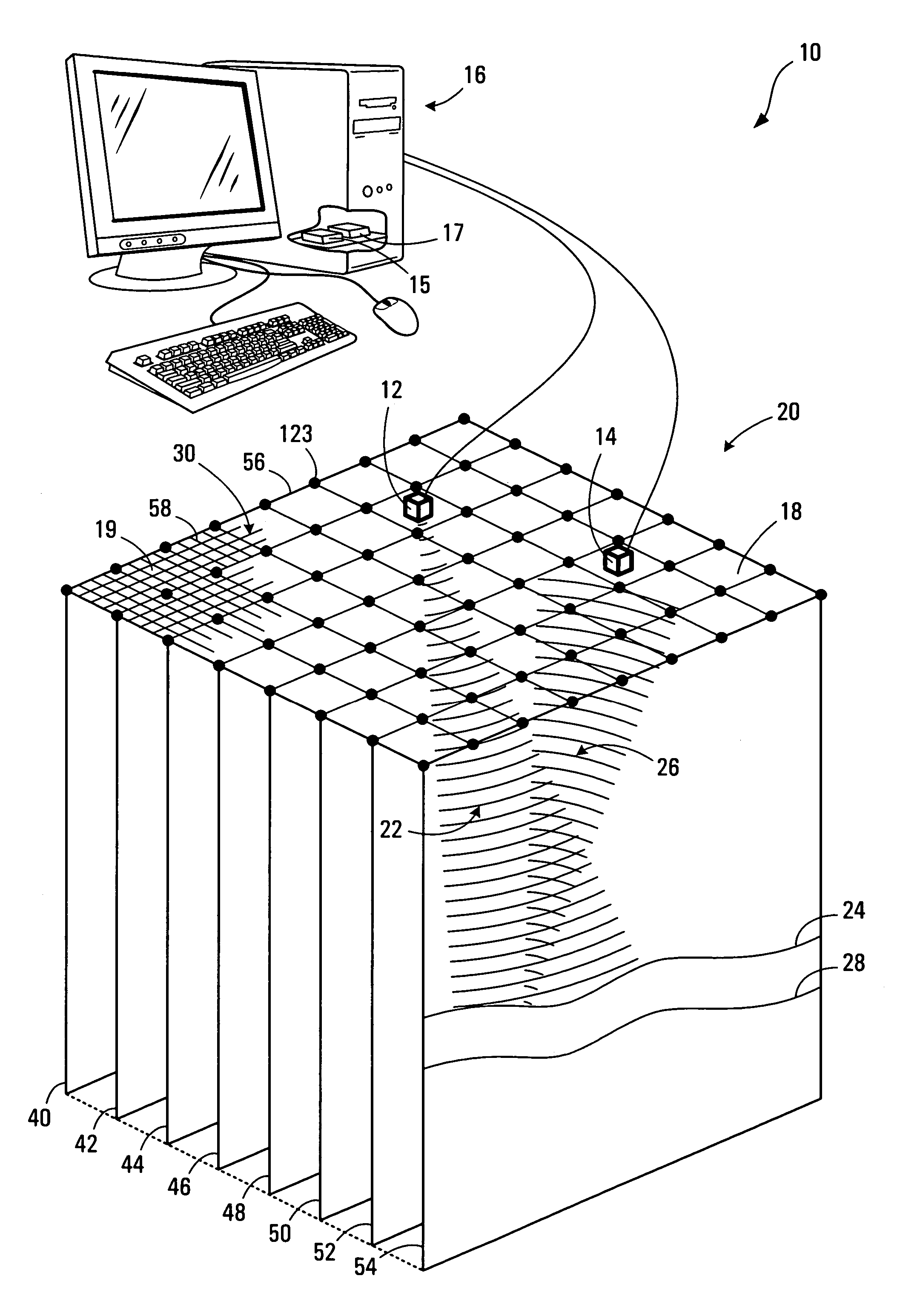
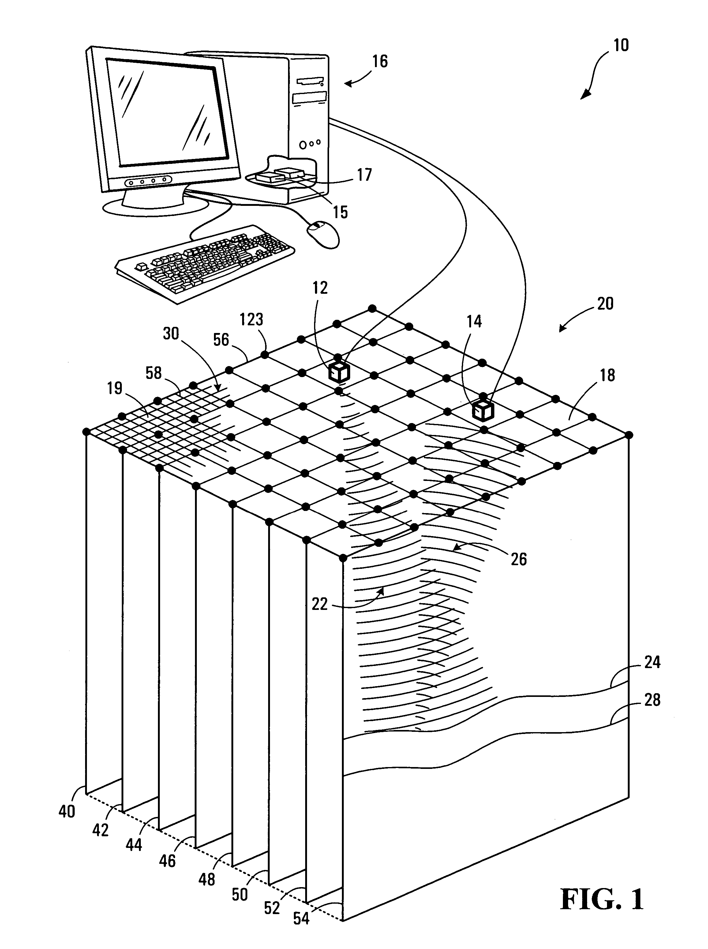
[0346]Referring to FIG. 1, a system according to a first embodiment of the invention is shown generally at 10. The system 10 includes a source 12 of seismic energy and at least one seismic receiver 14 in communication with a computer 16. When used on land, the seismic source 12 can be a high explosive charge electrically detonated in a borehole located at a selected point on a terrain 18 on the surface 20 of the earth, or another energy source having capacity for delivering a series of impacts or mechanical vibrations to the earth's surface 20, for example. An incident seismic wave 22 is generated in the earth's subsurface by the source 12 and is partially reflected back to the surface 20 from strata interfaces 24 and 28 as seismic reflections 26. These seismic reflections 26 reach different locations on the surface 20 of the earth at different times, depending on the distance and velocity characteristics of the subsurface traversed. The seismic receiver 14 is used to produce an ele...


PUM


Abstract

A method and apparatus for estimating a seismic velocity field from seismic data including time-amplitude representations associated with source-receiver locations spaced apart by an offset distance and having a midpoint therebetween, the seismic data being arranged into common midpoint (CMP) gathers associated with respective CMP locations. A control plane having an edge intersecting a plurality of the CMP locations is defined, an initial velocity field for the control plane is produced, the initial velocity field including a plurality of time-velocity values for each of the CMP locations; and an optimized velocity field for the control plane is produced by adjusting the time-velocity values for each of the CMP locations in response to trends, relative to offset distance, in time values, associated with common seismic events, until said optimized velocity field satisfies a condition.

Description

BACKGROUND OF THE INVENTION[0001]1. Field of Invention[0002]This invention relates to processing acoustic reflections to obtain velocity information for an acoustic medium and, in particular, processing seismic data to obtain a velocity field.[0003]2. Description of Related Art[0004]Acoustic energy in the form of reflected acoustic waves, such as conventional seismic reflections, are often detected and then processed to obtain a three-dimensional (3D) seismic velocity field associated with a 3D region within the earth's subsurface. The 3D velocity field typically includes velocity values approximating the velocity of a seismic wave travelling through corresponding points within the 3D region. The 3D velocity field may alternatively be expressed as a set of time-velocity curves. Each time-velocity curve is typically associated with a location on a surface of the 3D region and includes velocity values and associated time values. The time values represent the two-way travel time of sou...

Claims


Application Information

Patent Timeline
Patent Type & Authority Patents(United States)
IPC IPC(8): G01V1/00G01V1/28G06F19/00G01V1/30G06F17/10
CPCG01V1/303G01V1/345G01V1/362
Inventor STINSON, KERRY JAMESLEVY, SHLOMOCHAN, WAI-KINCRASE, EDWARD CHARLES
Owner DATA MODELING
Learn More