Check patentability & draft patents in minutes with Patsnap Eureka AI!

Head support system

a support system and head technology, applied in the field of surgical equipment, can solve the problems of inflexible and inconvenient cleaning, difficult to reach the pawl pin or locking screw under the surgical draping, time-consuming and distracting, etc., and achieve the effect of convenient disassembly and cleaning. , high flexibility

Active Publication Date: 2006-10-10
INTEGRA LIFESCI
View PDF21 Cites 81 Cited by
  • Summary
  • Abstract
  • Description
  • Claims
  • Application Information

AI Technical Summary

Benefits of technology

[0006]The present invention provides head support systems that are highly flexible and can be used with a wide range of imaging, neuro-navigational and surgical procedures. The head support systems of the present invention provide both static head support, for example, a horseshoe pad, other pads, pins, etc., and head stabilization, for example, a skull clamp or other devices. The head support systems of the present invention permit a head support to be adjusted and simultaneously locked at any elevation with a motion of only one hand. Further, the components of the head support systems of the present invention are easily disassembled for ease of cleaning. Such a combination of static load support and stabilization is especially useful when working with pediatric patients and in plastic surgery.
[0007]In accordance with the principles of the present invention and in accordance with the described embodiments, the present invention provides a head support system for use with a patient support, which provides support and stabilization for a patient's head. The head support system has a support structure with a crossbar extending transverse to, and connected to, the patient support. A head support is removably mountable to a portion of the support structure exclusive of the crossbar and provides a static support for the patient's head. A head stabilization device is removably mountable to the crossbar of the support structure and stabilizes the patient's head.

Problems solved by technology

In those situations where both subjacent support and lateral stabilization are required, having to mount both devices from the same crossbar member is complicated, inflexible and inconvenient.
Known head supports often use a pawl pin or locking screw to control elevation, and such pawl pin or locking screw are centrally located and difficult to reach beneath the surgical draping.
As can be appreciated, the presence of the draping makes such adjustments more difficult, time consuming and a distraction from the surgical procedure.

Method used


Image

  • Head support system
  • Head support system
  • Head support system

Examples


first embodiment

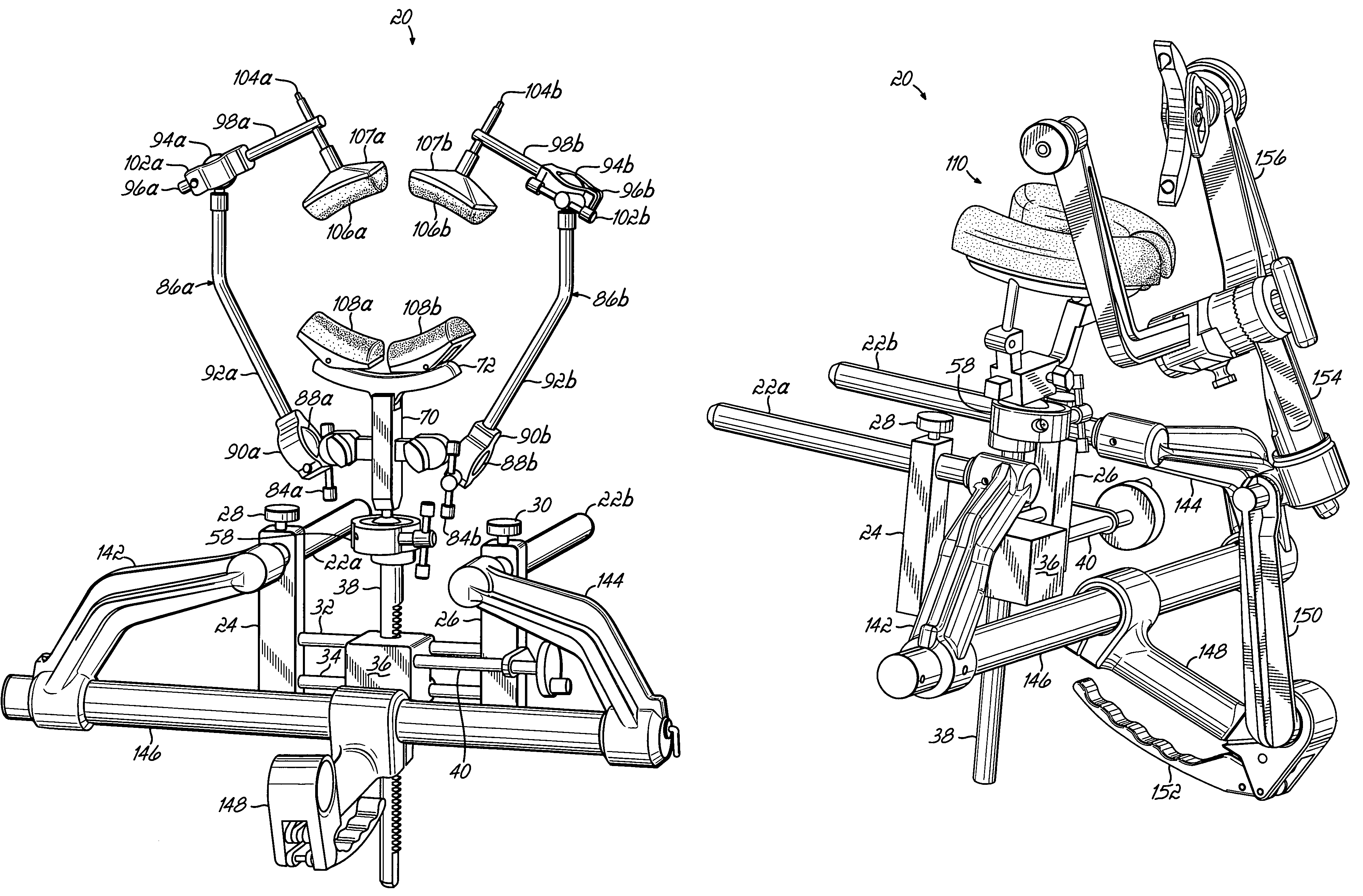
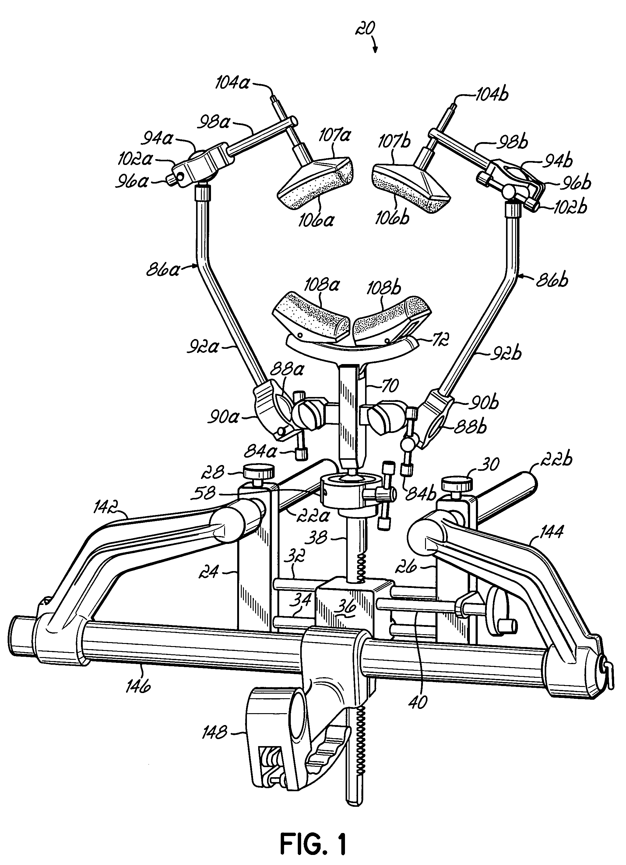
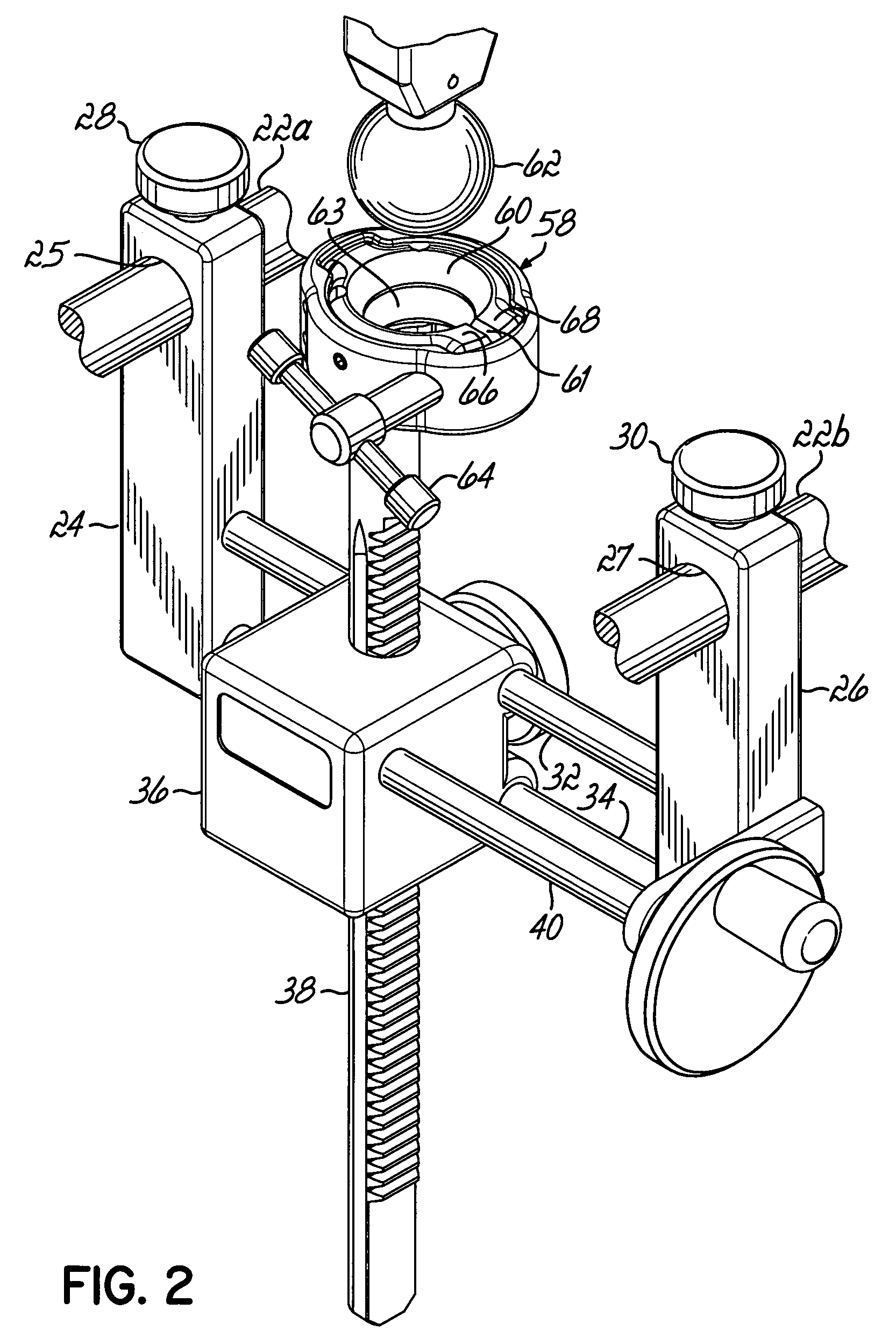
[0019]Referring to FIGS. 1 and 2, in a first embodiment, a head support system 20 is mounted on spaced-apart support shafts 22a, 22b that are connected to an end of a patient support (not shown), for example, an operating table in a known manner. The support shafts 22a, 22b extend substantially parallel with a length of the patient support. First and second support posts 24, 26 have respective bores 25, 27 that receive respective support shafts 22a, 22b, and the support posts 24, 26 can be locked at a desired position by means of respective locking screws 28, 30. Upper and lower guide rods 32, 34 have first ends fixed in a lower portion of the first support post 24. Opposite ends of the guide rods 32, 34 are supported in a lower portion of the second support post 26. The guide rods 32, 34 extend through a gear box housing 36, and thus, the housing 36 is slidable longitudinally along the guide rods 32, 34 but cannot rotate with respect thereto. Also extending through the housing 36 i...

second embodiment

[0024]the head support 20 is shown in FIGS. 6 and 7, wherein components identical to the components shown in, and described with respect to, FIGS. 1 and 2 are identically numbered. The support 70, rocker arm 72 and occiput pads 108 of FIG. 1 are replaced by a horseshoe support 110 having pads 136, 138 for supporting a patient's head. A ball 112 is attached to a fixed horseshoe bracket 114 and is sized to snap into the socket 60 to form a ball and socket joint identical to the ball and socket joint 58 previously described. Thus, the horseshoe support 110 is pivotable with respect to the socket 60 and can be locked at any desired orientation by tightening the locking screw 64.

[0025]Referring to FIG. 7, a horseshoe slide arm 116 is slidable within the fixed horseshoe bracket 114. Thus, the spacing or distance between left and right horseshoe arms 118, 120 can be adjusted. A locking screw 122 is threaded through the fixed horseshoe bracket 114 and can be brought to bear against the slid...


PUM


Abstract

A head support system for use with a patient support. The head support system has a support structure with a crossbar extending transverse to, and connected to, the patient support. A head support device is removably mountable to a portion of the support structure exclusive of the crossbar and provides a static support for the patient's head. A head stabilization device is removably mountable to the crossbar of the support structure and stabilizes the patient's head.

Description

[0001]This application claims the benefit of U.S. Provisional Application No. 60 / 526,047, filed on Dec. 1, 2003 and U.S. Provisional Application No. 60 / 544,863, filed on Feb. 13, 2004, all of which are hereby expressly incorporated by reference hereinFIELD OF THE INVENTION[0002]This invention relates to surgical equipment and more particularly, a head support system.BACKGROUND OF THE INVENTION[0003]During surgical procedures, one or more devices may be used to support a patient's head. For example, there may be a need to provide a static support for a patient's head; and typically, a static head support includes one or more pads that provide a static subjacent support of the patient's head in a prone or supine position. Such a static head support is mounted on a crossbar that extends transversely off the end of a patient support such as an operating table. Alternatively, a stabilization device, such as a skull clamp, is also used to support and stabilize a patient's head, and such a...

Claims


Application Information

Patent Timeline
Patent Type & Authority Patents(United States)
IPC IPC(8): A61G13/12
CPCA61B19/203A61G13/12A61G15/125A61G13/121A61G13/1295A61B90/14
Inventor DINKLER, II, CHARLES E.EASTON, KEVIN R.
Owner INTEGRA LIFESCI
Features
  • R&D
  • Intellectual Property
  • Life Sciences
  • Materials
  • Tech Scout
  • Unparalleled Data Quality
  • Higher Quality Content
  • 60% Fewer Hallucinations
Learn More