Radiator including a heat sink and a fan

a technology of radiators and fans, applied in the field of radiators, can solve the problems of increased manufacture costs of radiators, increased risk of fan falling due to unexpected shaking or vibration, and large amount of heat produced, and achieve the effect of stable configuration

Inactive Publication Date: 2006-10-10
HON HAI PRECISION IND CO LTD
View PDF20 Cites 20 Cited by
  • Summary
  • Abstract
  • Description
  • Claims
  • Application Information

AI Technical Summary

Benefits of technology

[0007]Accordingly, an object of the present invention is to provide a radiator which has a stable configuration.
[0008]Another object of the present invention is to provide a radiator which has a decrease in manufacture cost and an increase in production of the radiator.

Problems solved by technology

During operating of an electronic component such as a computer central processing unit (CPU), a large amount of heat is often produced.
As a result, manufacture cost of the radiator is increased.
Furthermore, once any one of the screws for mounting the fan to the heat sink is damaged, the fan is at the risk of falling due to unexpected shaking or vibration.
This adversely affects the heat dissipation efficiency of the radiator.
Additionally, it takes a long term to install four screws into the screw holes, especially in mass production.

Method used


Image

  • Radiator including a heat sink and a fan
  • Radiator including a heat sink and a fan
  • Radiator including a heat sink and a fan

Examples


Embodiment Construction

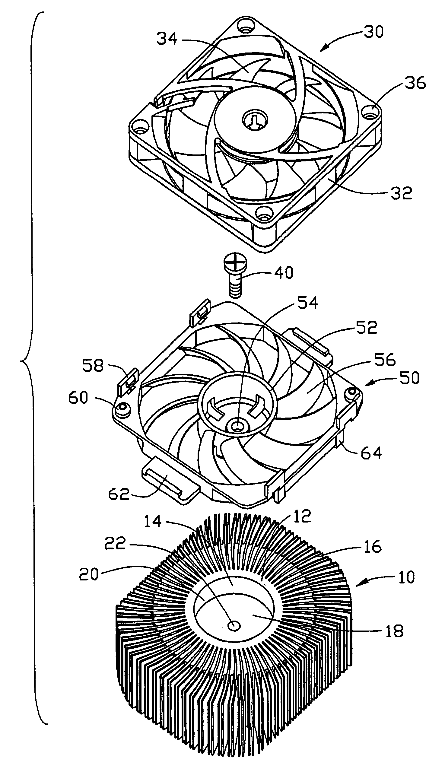
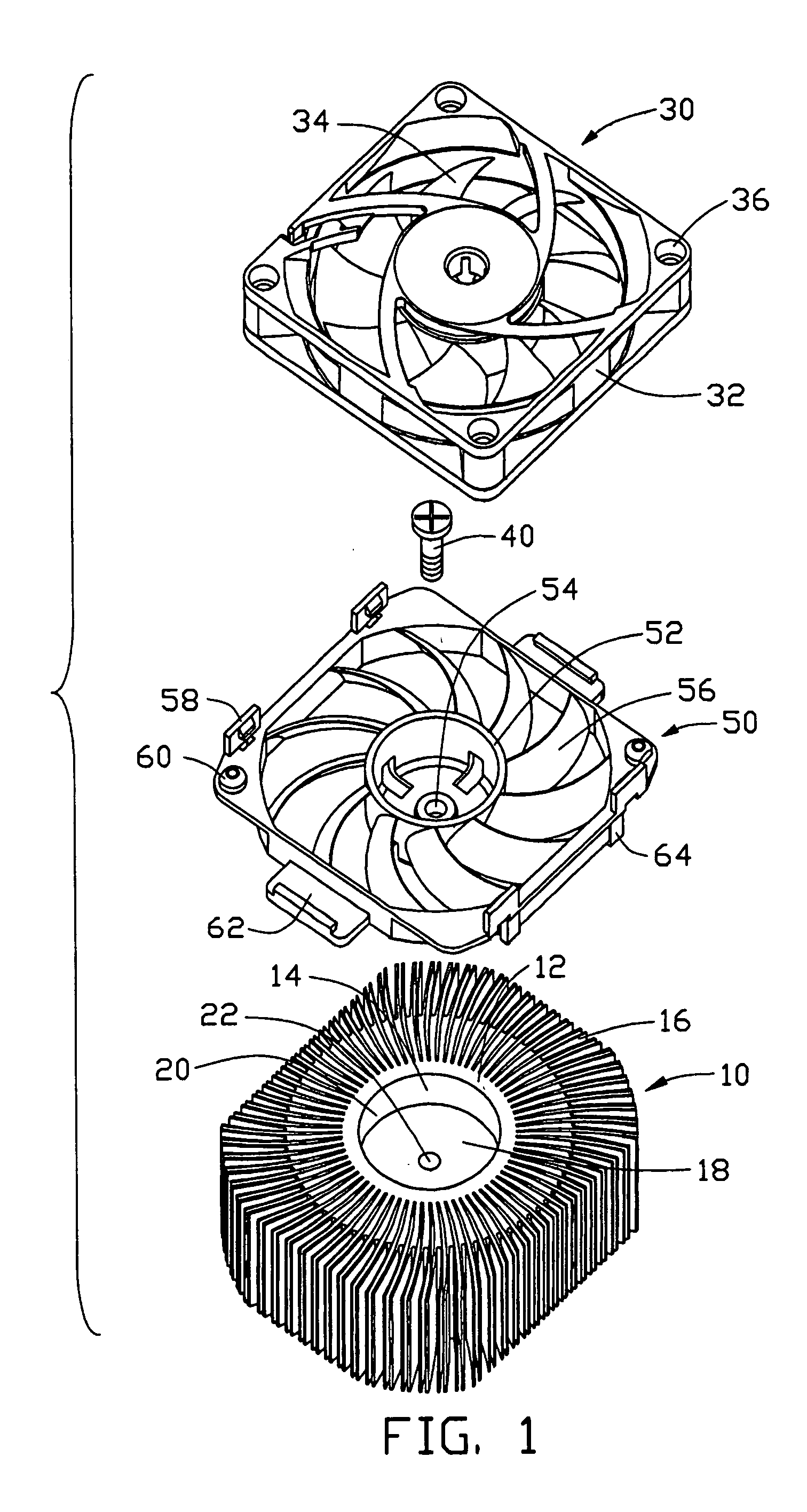
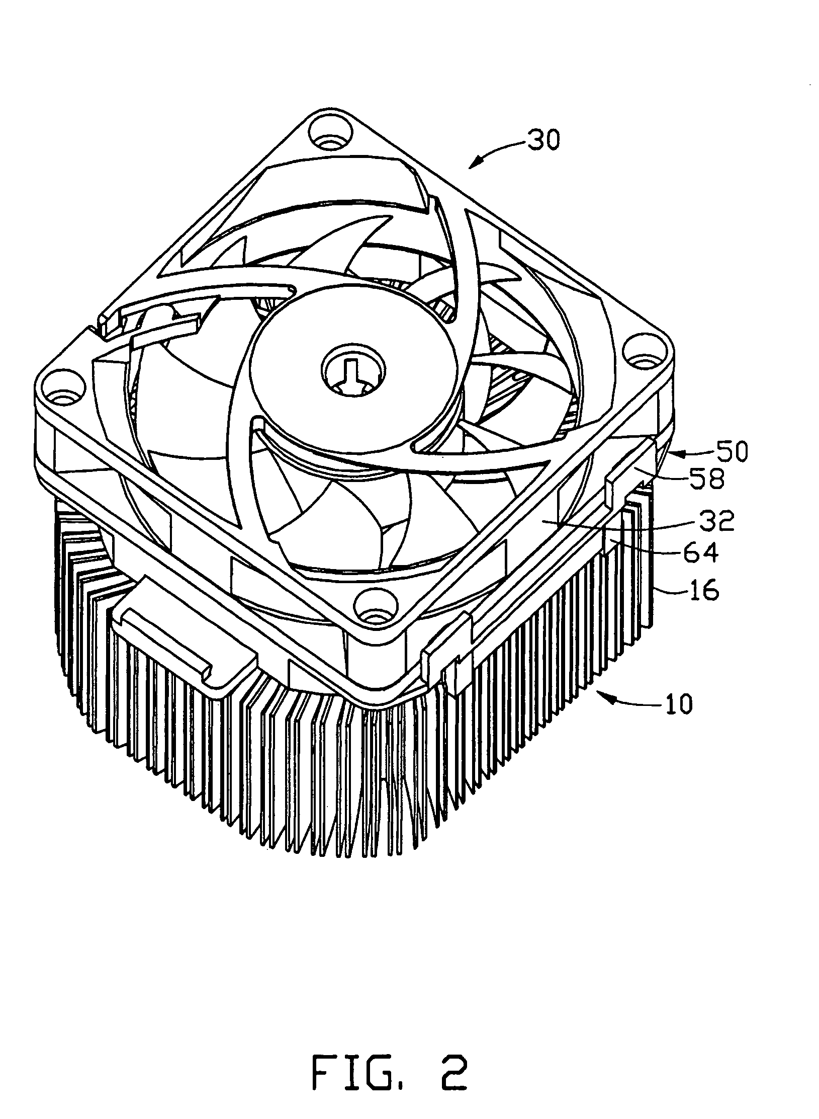
[0013]Referring to FIG. 1, a radiator in accordance with the preferred embodiment of the present invention is provided to remove heat from an electronic component (not shown), such as a central processing unit (CPU). The radiator comprises a heat sink 10, a fan 30 and a fan holder 50 for attaching the fan 30 to the heat sink 10.

[0014]The heat sink 10 comprises a cylindrical column 12 and a plurality of radial fins 16 radially extending from the circumference of the column 12. An axial channel 14 is defined in the column 12. The channel 14 interferentially receives a heat-conductive pillar 18 therein and therefore remains a cavity 20 right above the pillar 18. A hole 22, especially preferably to be a screw hole, is defined in a substantially central portion of an end of the pillar 18 in communication with the cavity 20. An opposite end of the pillar 18 is attachable to an electronic component (not shown), such as a chip, a central processing unit (CPU) or the like.

[0015]The fan 30 co...


PUM


Abstract

A radiator includes a heat sink (10), a fan holder (50) and a fan (30). The heat sink includes a heat-absorbing member (12, 18) that defines a cavity (20) in an end thereof. The fan holder includes a central hub (52) secured into the cavity of the heat sink. The fan is positioned to the heat sink via the fan holder.

Description

BACKGROUND OF THE INVENTION[0001]1. Field of the Invention[0002]The present invention relates to radiators for removing heat from electronic components, and more particularly to a radiator including a heat sink and a fan mounted on the heat sink for enforcing air convection.[0003]2. Description of Related Art[0004]During operating of an electronic component such as a computer central processing unit (CPU), a large amount of heat is often produced. The heat must be quickly removed from the CPU to prevent it from becoming unstable or being damaged.[0005]Typically, a heat sink is attached to an outer surface of the CPU to facilitate removal of heat therefrom. A fan is mounted on top of the heat sink to enhance heat dissipation efficiency.[0006]U.S. Pat. No. 6,017,185 disclosed a radiator in which the fan is mounted to the heat sink via four screws. Correspondingly, four screw holes are defined in a base of the heat sink. The screw holes should be evenly distributed on the base and each...

Claims


Application Information

Patent Timeline
Patent Type & Authority Patents(United States)
IPC IPC(8): H05K7/20H01L23/467
CPCH01L23/467H01L2924/0002H01L2924/00
Inventor KU, CHIN-LONGCHAN, PO-HAN
Owner HON HAI PRECISION IND CO LTD
Why Eureka
Try Eureka