

Support structure for transversal engine
a technology for supporting structures and engines, applied in the direction of machine supports, shock absorbers, jet propulsion mountings, etc., can solve problems such as durability drawbacks, and achieve the effect of improving riding comfor
- Summary
- Abstract
- Description
- Claims
- Application Information
AI Technical Summary
Benefits of technology
Problems solved by technology
Method used
Image

Examples
first embodiment
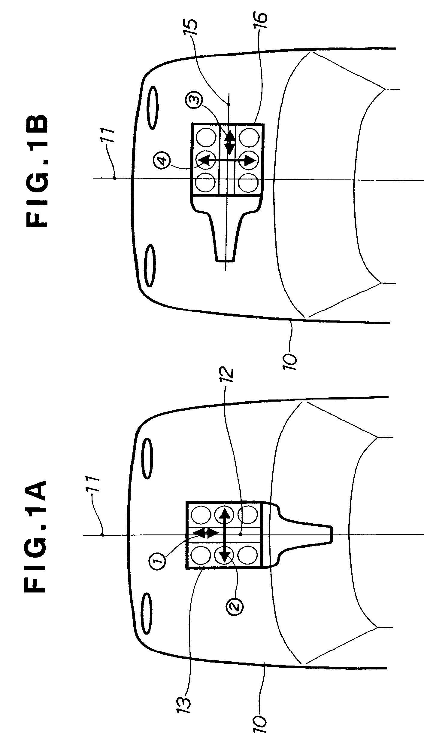
[0082]Now, reference is made to FIG. 4A illustrating in top plan the transversal engine mount according to the present invention and FIG. 4B illustrating the engine mount as viewed in the direction of arrows b—b.
[0083]In FIG. 4A, reference numeral 16 denotes a transversal engine, reference numeral 53 denotes a transmission which is attached to the engine 16, reference numeral 54 denotes a power plant which is obtained by combining the engine 16 and the transmission 53, reference numerals 55 and 55 denote drive shafts, reference numerals 56 and 56 denote drive wheels, and reference numeral 57 denotes a center of mass of the power plant 54.
[0084]That is, there is shown a well known structure which changes a power generated in the transversal engine 16 so as to transmit to the drive wheels 56 and 56 via the drive shafts 55 and 55.
[0085]Then, two inclined hydro mounts 20 and 20, one vertical type hydro mount 40 and two rubber mounts 60 and 60 are arranged in such a manner as to surround...
second embodiment
[0098]Reference is now made to FIG. 6A illustrating in top plan a transversal engine mount according to the present invention, and FIG. 6B illustrating the engine mount as viewed in the direction of arrows b—b. Since reference numerals used in these Figures are the same as those used in FIGS. 4A and 4B, description thereof will be omitted.
[0099]As shown in FIG. 6A, the inclined hydro mount 20 is arranged in a rear side of the power plant 54 and inside the whole width W. The vertical type hydro mount 40 is arranged in front of the power plant 54.
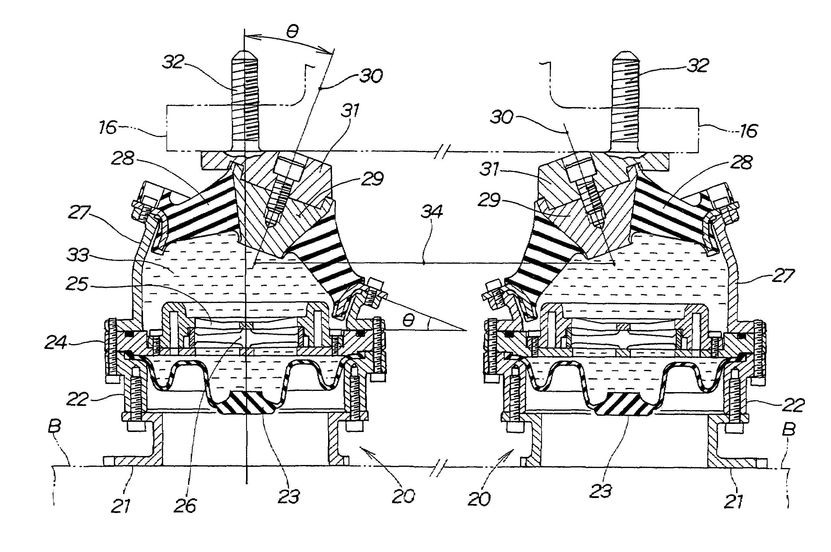
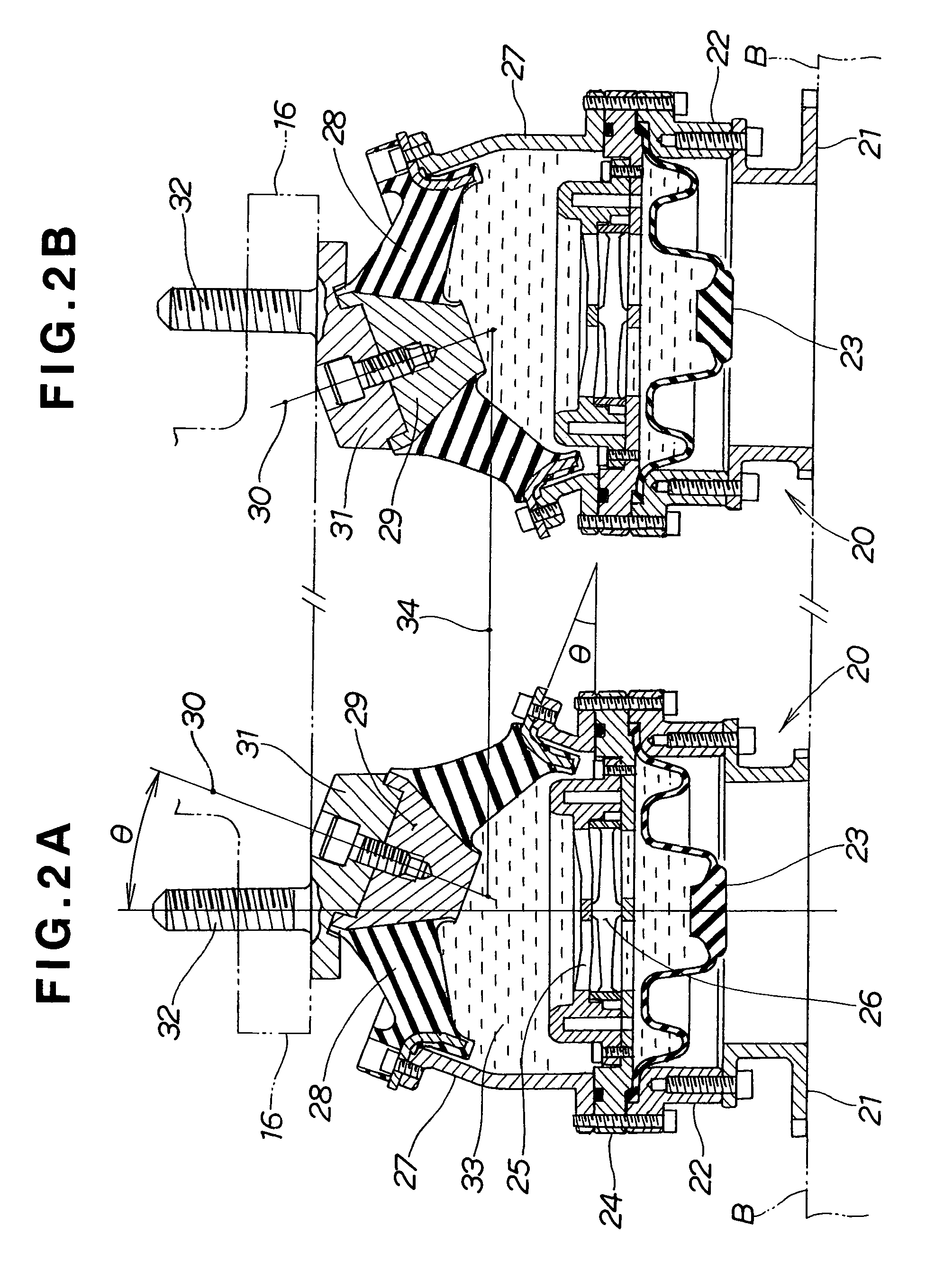
[0100]Further, as shown in FIG. 6B, the height of the inclined hydro mount 20 is determined in such a manner as to substantially coincide with a level line 58 passing through the center of mass 57 of the power plant 54. The height center line of the inclined hydro mount 20 is the one designated by numeral 34 in FIG. 2. The center line 34 is made consistent with or close to the level line 58.
[0101]Now, reference is made to FIGS. 7A and 7B illu...
third embodiment
[0107]Next, reference is made to FIG. 8A illustrating in top plan an engine mount for the transversal engine, according to the present invention, and FIG. 8B illustrating the engine mount as viewed in the direction of arrows b—b of FIG. 8A.
[0108]As shown in FIG. 8A, inclined hydro mounts 20F and 20R are arranged in front and rear sides of the power plant 54. These inclined hydro mounts 20F and 20R are both arranged inside the whole width W of the power plant 53.
[0109]As shown in FIG. 8B, the rear inclined hydro mount 20R is arranged H2 above the center of mass 57, and the front inclined hydro mount 20F is arranged H3 below the center of mass 57.
[0110]In the case that the distance H2 is substantially equal to the distance H3, the moments can be cancelled, and it is possible to purely burden the inclined hydro mounts 20F and 20R with the longitudinal vibration.
[0111]That is, the third embodiment is characterized in that a plurality of inclined hydro mounts 20F and 20R are provided, an...
PUM
 Abstract
Description
Claims
Application Information