Front pillar garnish

a front pillar and garnish technology, applied in the field of front pillar garnish, can solve the problems of limiting the height in view of design and whistling sound, affecting the front pillar garnish, so as to achieve excellent front field of view, wide wiper wiping area, and increased volume of rainwater gutters

Active Publication Date: 2006-10-10
TOKAI KOGYO CO LTD +1
View PDF13 Cites 12 Cited by
  • Summary
  • Abstract
  • Description
  • Claims
  • Application Information

AI Technical Summary

Benefits of technology

[0007]In view of the above-described problem, an object of the present invention is to provide a pillar garnish capable of ensuring a wide field of view in running under rainy weather and capable of securing a sufficient volume of rain water gutter for making rainwater on a window pane wiped and collected by a wiper smoothly flow along the rain water gutter of the pillar garnish and preventing a lateral flow of rainwater toward a side window.

Problems solved by technology

In enlarging the volume, a height of the rain water gutter that extends to a lower side may be increased, however, there is a limit in an allowable height in view of design and whistling sound that is generated during running.
That can be achieved if a length of the wiper blade is prolonged, however, there is a concern that in operating the wiper, particularly when the wiper reaches a lowest side, (when wiper is stopped), the wiper interferes with the pillar garnish.

Method used


Image

  • Front pillar garnish
  • Front pillar garnish
  • Front pillar garnish

Examples


first embodiment

[First Embodiment]

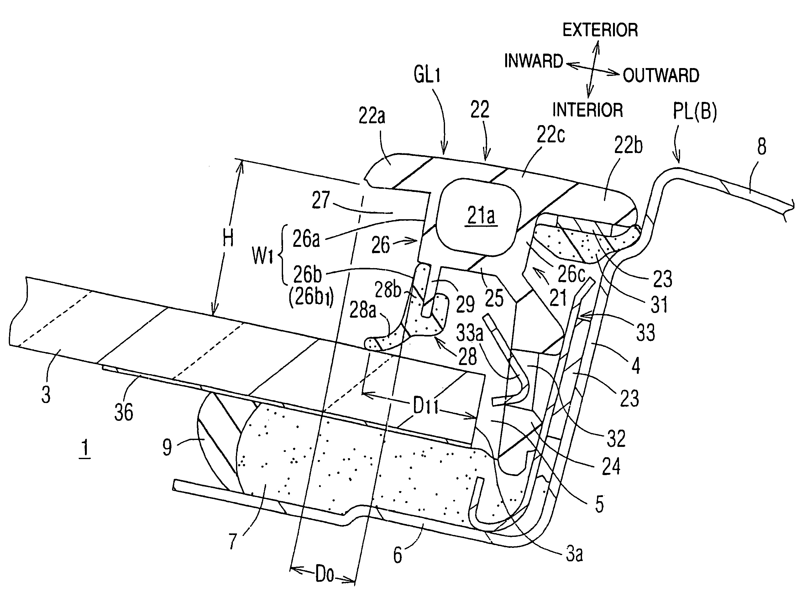
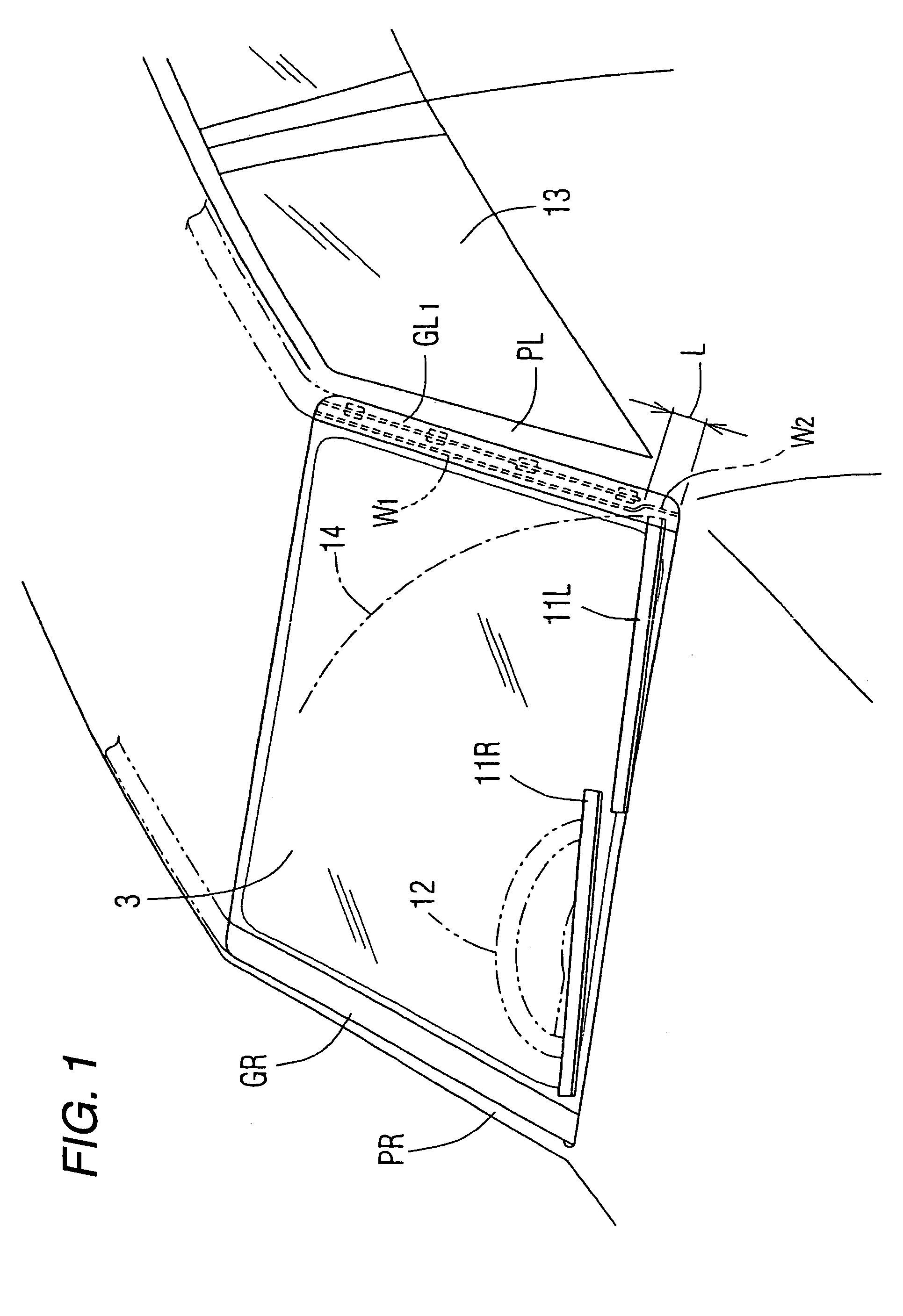
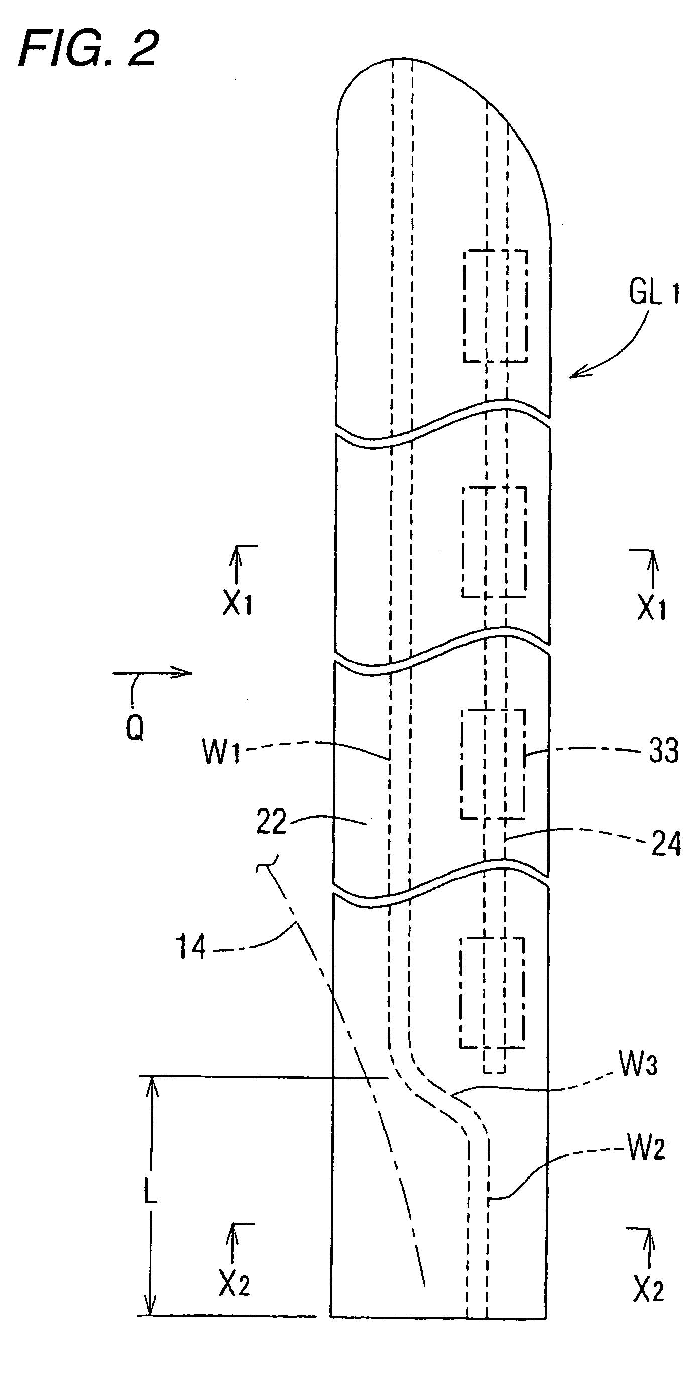
[0029]FIG. 1 is a perspective view viewed from a skewed upper direction and showing a portion of a front window of an automobile in which a pillar garnish GL1 according to a first embodiment of the invention is attached to a front pillar PL on a left side. FIG. 2 is a schematic front view of the pillar garnish GL1 on the left side. FIG. 3 is a schematic view of aback surface of the pillar garnish GL1 shown FIG. 2. FIG. 4 is a schematic view (schematic side view) viewed from a Q arrow mark direction in FIG. 2. FIG. 5 is a partial perspective view viewed from a skewed lower direction and showing a second groove wall W2 of a lower end portion of the pillar garnish GL1 on the left side. FIG. 6 is an enlarged sectional view taken along a line X1—X1 in FIG. 2 when the pillar garnish GL1 on the left side is attached. FIG. 7 is an enlarged sectional view taken along a line X2—X2 in FIG. 2. As shown in FIG. 1, FIG. 6 and FIG. 7, both side portions of a window opening 1 for ...

second embodiment

[Second Embodiment]

[0040]FIG. 8 is a front view of a pillar garnish GL2 on a left side according to a second embodiment of the invention. FIG. 9 is a partial perspective view viewed from a skewed lower direction and showing a portion of a second groove wall W2′ at a lower end portion of the pillar garnish GL2. The pillar garnish GL2 shown in FIG. 8 and FIG. 9 differs from the pillar garnish GL1 of the first embodiment only in a shape of the second groove wall W2′ at the lower end portion in the longitudinal direction and other portions thereof are the same. That is, a lower groove wall 26b′ of the second groove wall W2′ is shifted in a width direction considerably as proceeding to a lower end in the longitudinal direction of the pillar garnish GL2, and an extended plate portion 34′ and the lower groove wall 26b′ are connected by a connecting portion 35′ a width of which is widened as proceeding to the lower end in the longitudinal direction of the pillar garnish GL2. Therefore, alth...


PUM


Abstract

A front pillar garnish includes an ornamental head portion having an inward end, a groove wall protruding the ornamental head portion toward a window pane and defining a rain water gutter in cooperation with a surface of the window pane, and amounting leg portion protruding from the ornamental head portion toward a gap between the window pain and a front pillar for mounting the front pillar garnish. The groove wall includes first and second groove walls respectively positioned at an upper side and a lower side in a longitudinal direction of the front pillar garnish. A maximum distance in a direction toward an outer peripheral end face of the window pane from the inward end of the ornamental head portion to the second groove wall is larger than a maximum distance from the inward end of the ornamental head portion to the first groove wall.

Description

BACKGROUND OF THE INVENTION[0001]1. Field of the Invention[0002]The present invention relates to a front pillar garnish to be attached along a front pillar that constitutes a portion of a window opening of a vehicle body for covering a gap between a front window pane and the front pillar.[0003]2. Description of the Related Art[0004]Various constitutions of the front pillar garnish (hereafter also called as “pillar garnish”) have been proposed and known (for example, see JP-A-2003-54262). A pillar garnish disclosed in JP-A-2003-54262 integrally includes an ornamental head portion separated from a window pane surface to a vehicle exterior side and covering the gap at the separated position from the vehicle exterior side when the pillar garnish is attached to a predetermined position of a body panel, a groove wall defining a rain water gutter in cooperation with the window pane surface by being protruded from a back surface side of an inward portion of the ornamental head portion, and ...

Claims


Application Information

Patent Timeline
Patent Type & Authority Patents(United States)
IPC IPC(8): B60J7/00B60J1/02B60J1/20B60R13/02
CPCB60J1/2005B60J10/0045B60J10/0051B60J10/02B60J10/25B60J10/265B60J10/70
Inventor HARA, KENGOSAKAMOTO, KOICHI
Owner TOKAI KOGYO CO LTD
Why Eureka
Try Eureka