Illumination device for simulating channel letters

a technology of illumination device and channel letter, which is applied in the direction of illuminated signs, display means, instruments, etc., can solve the problems of large energy consumption, high voltage operation, and/or short life of light sources, and achieve the effect of small energy consumption

Inactive Publication Date: 2006-10-10
ILIGHT TECH INC
View PDF91 Cites 23 Cited by
  • Summary
  • Abstract
  • Description
  • Claims
  • Application Information

AI Technical Summary

Benefits of technology

[0007]The present invention meets the above identified needs, and others, by providing an illumination device for simulating channel letters that emits uniform and bright light devoid of hot spots; incorporates a light source that is lightweight, resilient, and long-lasting; operates at low voltages; consumes small amounts of energy; and can generate light of various colors.

Problems solved by technology

For example, such light sources often have a relatively short life, operate at high voltages, consume large amounts of energy, and / or are fragile.
Additionally, with regard to neon lighting, it is both fragile and heavy, primarily due to its supporting infrastructure, making it expensive to package or ship.
Moreover, it is extremely awkward to initially handle, install, and / or replace neon lighting.
LEDs are not only lightweight and resilient, but, when compared to other light sources, have a long life, operate at low voltages, and consume small amounts of energy.
Despite these benefits, the attributes of uniformity and brightness have proven to be difficult to produce in illumination devices incorporating LEDs.
For example, the lenses often used in channel letters do not sufficiently diffuse the light emanating from each LED to eliminate hot spots.

Method used


Image

  • Illumination device for simulating channel letters
  • Illumination device for simulating channel letters
  • Illumination device for simulating channel letters

Examples


Embodiment Construction

[0019]The present invention is an illumination device using high-intensity, low-voltage light-emitting diodes that is ideally adapted for applications in which common channel letters are currently used.

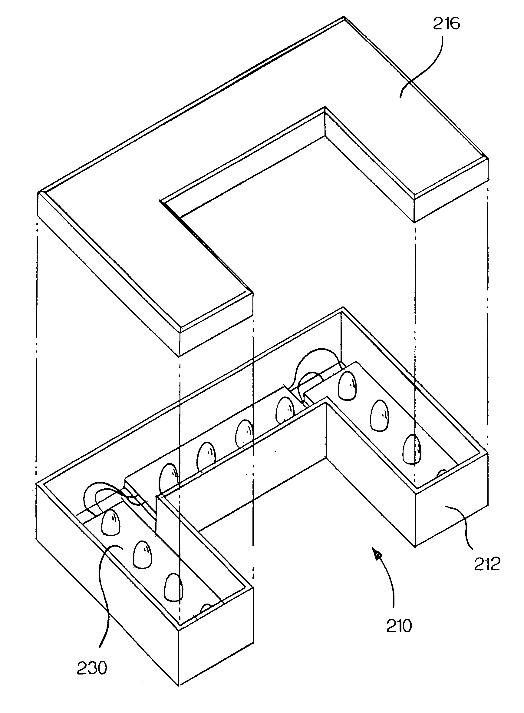
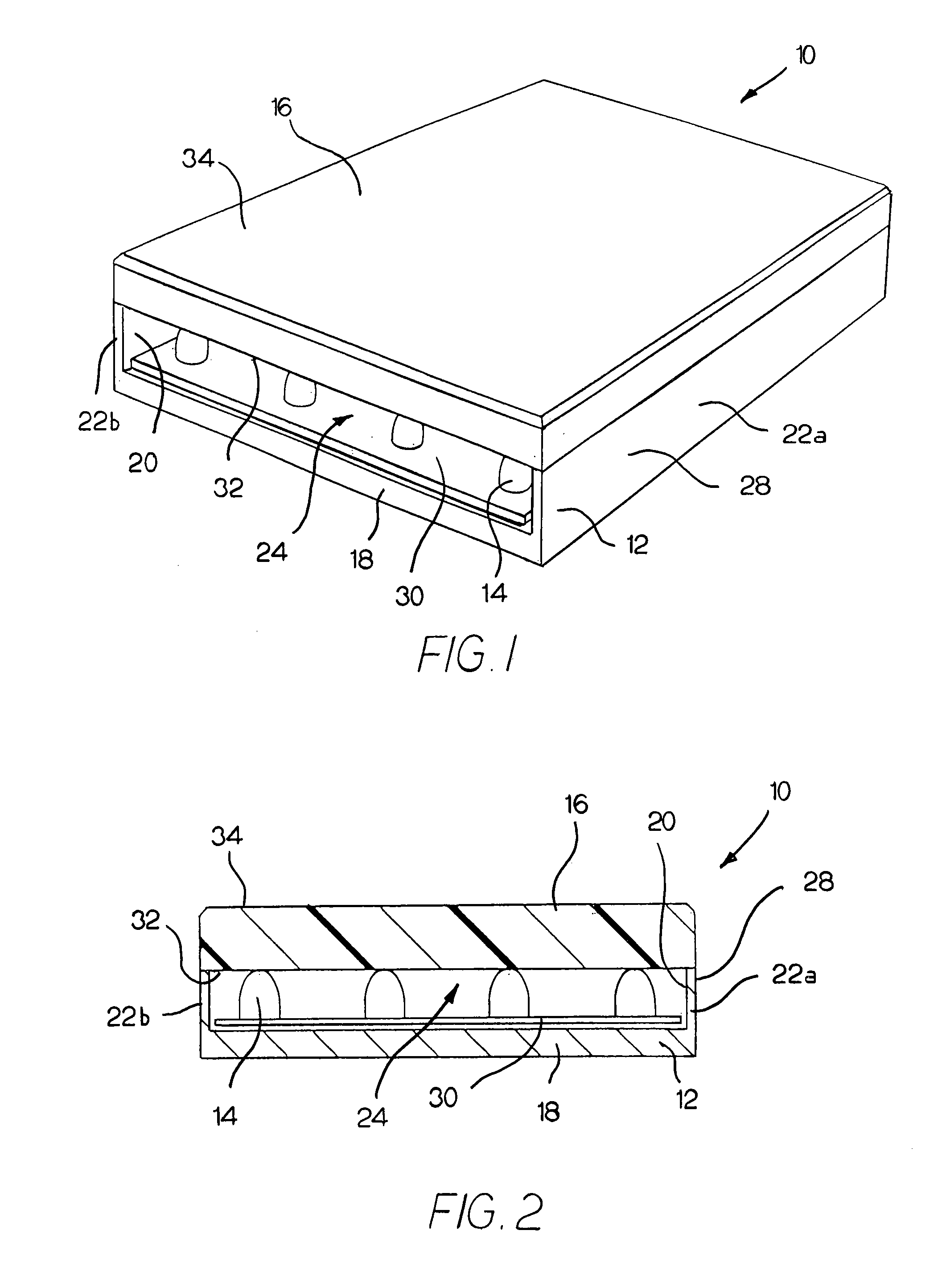
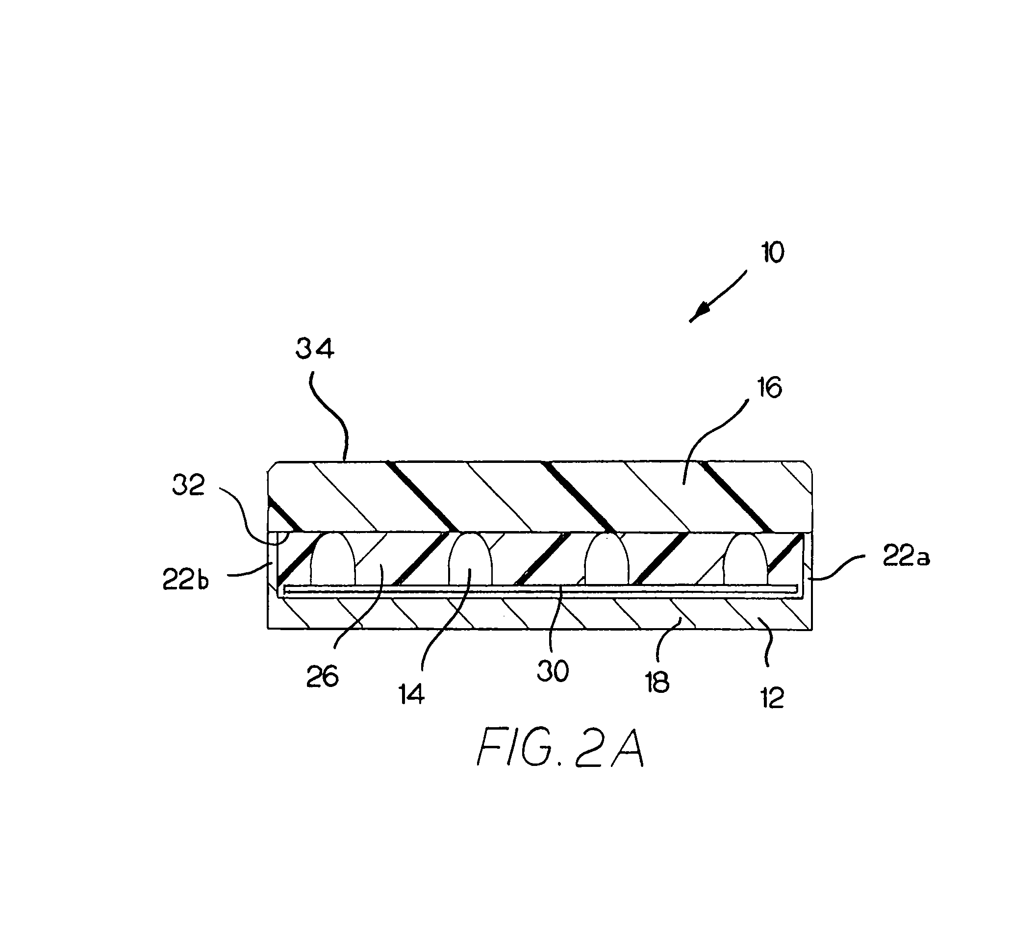
[0020]Referring to FIGS. 1–3, an exemplary embodiment of an illumination device 10 made in accordance with the present invention generally comprises a housing 12, a light source 14, and a scattering member 16. The housing 12 includes side walls 22a, 22b that extend upwardly from a base portion 18 to define an interior cavity 24. As shown in FIGS. 1–3, in this exemplary embodiment, these side walls 22a, 22b are integral with the base portion 18; however, in alternate embodiments, a separate, continuous side wall may circumscribe the base portion 18 to define the interior cavity 24.

[0021]The light source 14 is positioned within the interior cavity 24. In this exemplary embodiment, the light source 14 is comprised of a series of point light sources, such as high-intensity LEDs, which are...


PUM


Abstract

An illumination device generally comprises a housing, a light source, and a scattering member. The housing includes a base portion and a side wall, which collectively defines an interior cavity with an open end having a predetermined shape. A light source is positioned within the interior cavity, along with an electric connecting member adapted to connect the light source to a remote power source. A scattering member having substantially the same predetermined shape as the open end of the housing is positioned adjacent the light source at the open end of the interior cavity. The scattering member has a light-emitting surface and is composed of a material which causes light entering the scattering member to be directed through a portion of thereof before being scattered and emitted, such that a substantially uniform light pattern is perceived along the light-emitting surface of the scattering member in the predetermined shape.

Description

CROSS REFERENCES TO RELATED APPLICATIONS[0001]This application claims priority from U.S. Provisional Application Ser. No. 60 / 473,673 filed May 23, 2003, the entire disclosure of which is incorporated herein by this reference.FIELD OF THE INVENTION[0002]The present invention relates to illumination devices using high-intensity, low-voltage light-emitting diodes that may be adapted for applications in which common channel letters are used.BACKGROUND OF THE INVENTION[0003]Channel letters are commonly used to provide signage on buildings, specifically when it is desirable to view the signage at night or from a distance. A common channel letter is constructed of an enclosure that outlines the desired shape, such as the shape of a letter or other alphanumeric character. This enclosure has a substantially flat rear surface for attachment to a building, and more importantly, is designed to house a light source such as an incandescent lamp, fluorescent lighting, or neon lighting. Finally, th...

Claims


Application Information

Patent Timeline
Patent Type & Authority Patents(United States)
IPC IPC(8): F21V3/04
CPCG09F13/0404G09F13/22
Inventor CHAMBERS, JOE A.CLEAVER, MARK J.DOMINICK, JOHN R.ERIKSSON, ERIC OLAVHULSE, GEORGE R.
Owner ILIGHT TECH INC
Why Eureka
Try Eureka