
Computer input/output connector assembly

a technology for connecting parts and computers, applied in computing, coupling device connections, instruments, etc., can solve the problems of difficult access for users, laborious and expensive screwing of connector ports onto computer housings, and little flexibility to change the type of connector ports being used, so as to achieve the effect of easy snapping into a metal retaining brack

Inactive Publication Date: 2006-10-10
NORTHSTAR SYST CORP
View PDF7 Cites 51 Cited by
  • Summary
  • Abstract
  • Description
  • Claims
  • Application Information

AI Technical Summary

Benefits of technology

"The present invention is a computer input / output connector assembly that allows for easy attachment to a computer housing. The assembly includes connector port holders that can be easily snapped into a metal retaining bracket, making it simple to replace individual holders. The bracket is mounted on the front of a personal computer tower and includes holders for USB, IEEE 1394, audio, and video ports. The holders are made of durable plastic and securely snap into the bracket using movable cantilever strips and lock tabs. The bracket also includes EMI contact strips and small springs or tabs to ensure proper grounding of each connector port. Overall, the invention provides a simple and flexible way to connect a computer's input / output devices."

Problems solved by technology

Historically, connector ports have been located at the rear of the computer housing where they are difficult for the user to access.
All of this screwing of connector ports onto a computer housing is labor intensive and, therefore, expensive.
Moreover, present techniques for installing connector ports onto a computer housing allow little flexibility to change the type of connector ports being used if the manufacturer wants to use the same connector assembly for both high end computers with many connector ports and low end computers with fewer connector ports.

Method used


Image

  • Computer input/output connector assembly
  • Computer input/output connector assembly
  • Computer input/output connector assembly

Examples


Embodiment Construction

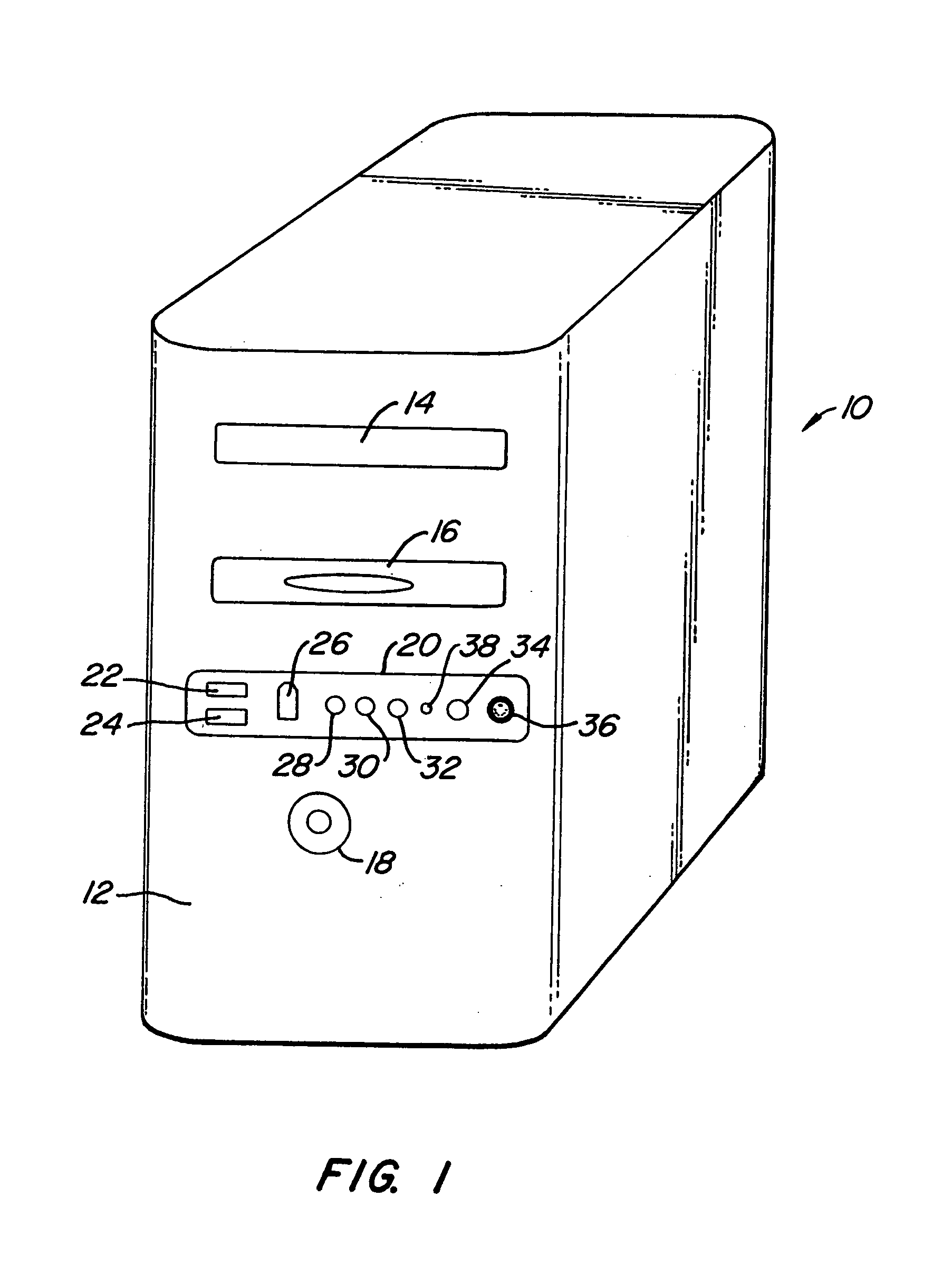
[0013]Referring now to FIG. 1, a tower 10 of a personal computer is shown. This computer tower 10 would typically house the circuitboards and chipsets which would perform most of the computer's operations. In many personal computers, this tower 10 would be connected to, among other things, a video monitor, keyboard, mouse and printer (not shown). On the front 12 of this personal computer tower 10 are numerous buttons and ports to allow the user to control operation of the personal computer. In the present embodiment, these buttons and ports, include a port for a CD / DVD drive 14, a port for a floppy disk drive 16, a power button 18 and an input / output connector assembly 20 of the present invention.

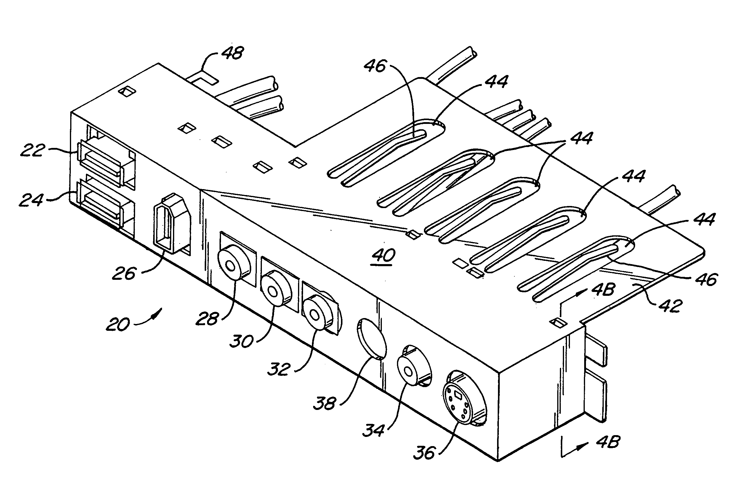
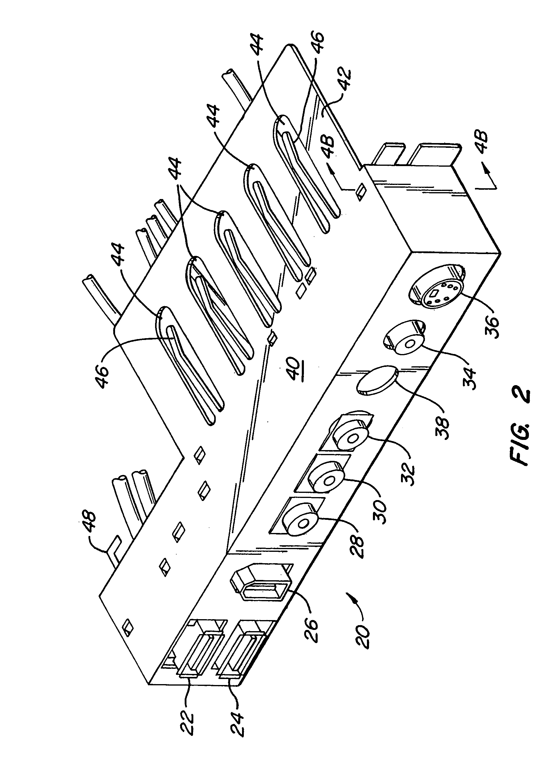
[0014]In the preferred embodiment, the input / output connector assembly 20 includes two USB connector ports 22, 24, an IEEE 1394 high speed communications port 26, a green audio out port28, a red microphone port 30, a blue audio in port 32, a yellow RCA video connector port 34, an S-video co...


PUM


Abstract

A computer input / output connector assembly which uses connector port holders that can easily be snapped into a metal retaining bracket. In one preferred embodiment, the bracket of the present invention is mounted on the front of a personal computer tower. Connected to the bracket is a first connector port holder with two USB connector ports, a second connector port holder with an IEEE 1394 high speed communication port, a third connector port holder with three audio ports (e.g., audio in, audio out and microphone) and a fourth connector port holder with two video ports (e.g., RCA composite video and S-video). The connector port holder is preferably made of a durable, heat resistant plastic. This connector port holder includes movable cantilever strips with lock tabs which can firmly snap into holes in the bracket for mounting.

Description

TECHNICAL FIELD OF THE INVENTION[0001]The present invention relates to an assembly for allowing input and / or output connections to be made to an electrical device, such as a personal computer. More particularly, a computer attachable bracket is provided which accepts snap-in connector port holders for allowing audio, visual, network, phone, modem and other input / output connections to be made to the computer.BACKGROUND OF THE INVENTION[0002]Computers have become an essential part of modern business. Through advances in chip design and manufacture, the cost of personal computers has dropped dramatically in recent years to the point where such personal computers are affordable by most consumers. As part of an effort to lower manufacturing costs, manufacturers have been looking for ways to more easily, reliably and flexibly assemble their computers.[0003]While much attention has been paid to advances in chip design and manufacture, comparatively little effort has been put into optimizin...

Claims


Application Information

Patent Timeline
Patent Type & Authority Patents(United States)
IPC IPC(8): H01R13/66G06F1/16H01R13/506H01R13/518H01R13/60H01R13/639
CPCG06F1/182H01R13/518H01R13/506
Inventor SPEARS, LOUIS E.THUNELL, ROBERT G.
Owner NORTHSTAR SYST CORP
Learn More