Grinding apparatus and method

a technology of grinding apparatus and grinding method, which is applied in the direction of edge grinding machine, grinding machine components, manufacturing tools, etc., can solve the problems of large wafers occupying a lot of floor space, extreme flatness and surface finishing requirements for both sides of the wafer, and loss of mechanical ruggedness

Active Publication Date: 2006-10-10
REVASUM INC +1
View PDF21 Cites 25 Cited by
  • Summary
  • Abstract
  • Description
  • Claims
  • Application Information

AI Technical Summary

Problems solved by technology

However, for larger wafers, such as the 300 mm diameter size now growing in popularity, extremely demanding flatness and surface finishing is required for both sides of the wafers.
Gross chemical and atomic-level forces also are imparted to the in...

Method used


Image

  • Grinding apparatus and method
  • Grinding apparatus and method
  • Grinding apparatus and method

Examples


Embodiment Construction

[0036]The following description is not to be taken in a limiting sense, but is made merely for the purpose of describing the general principles of the invention. The scope of the invention should be determined with reference to the claims.

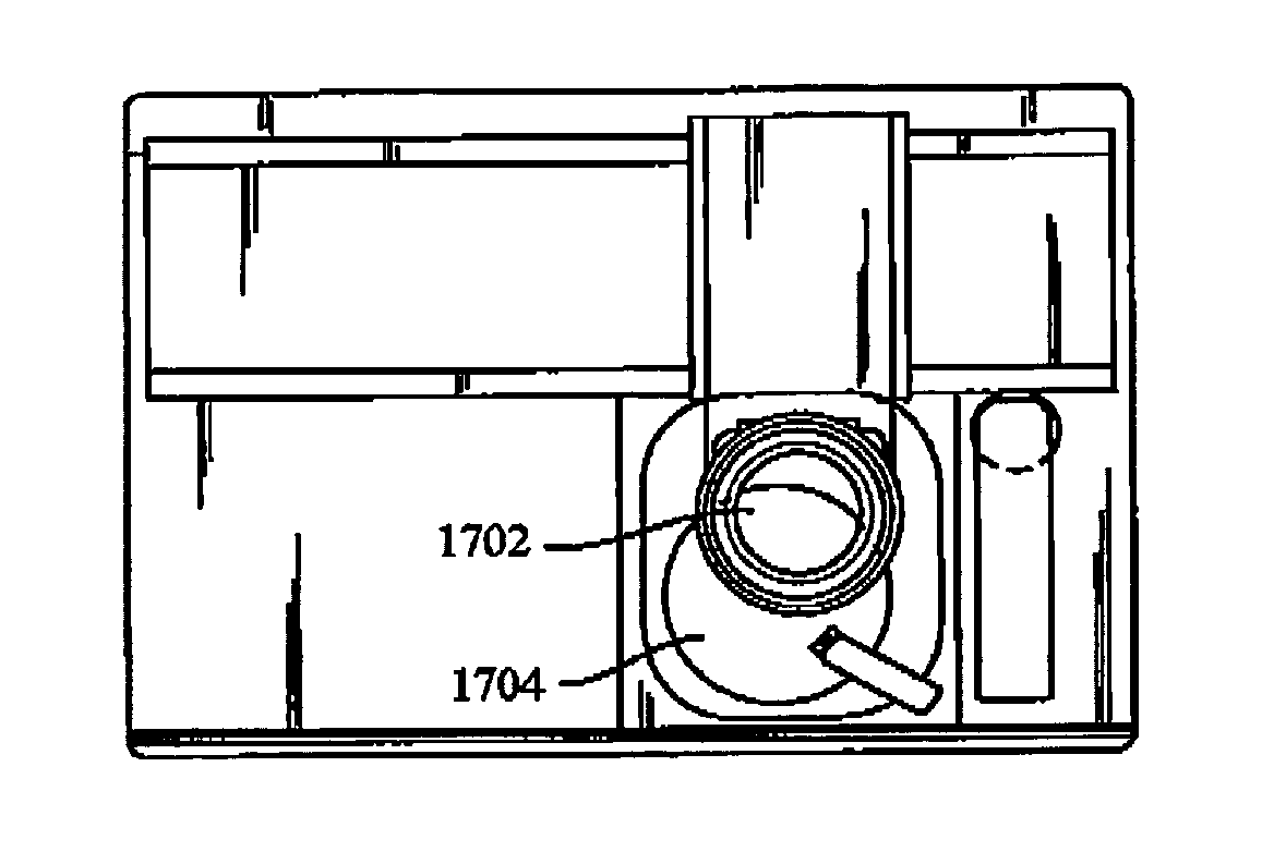
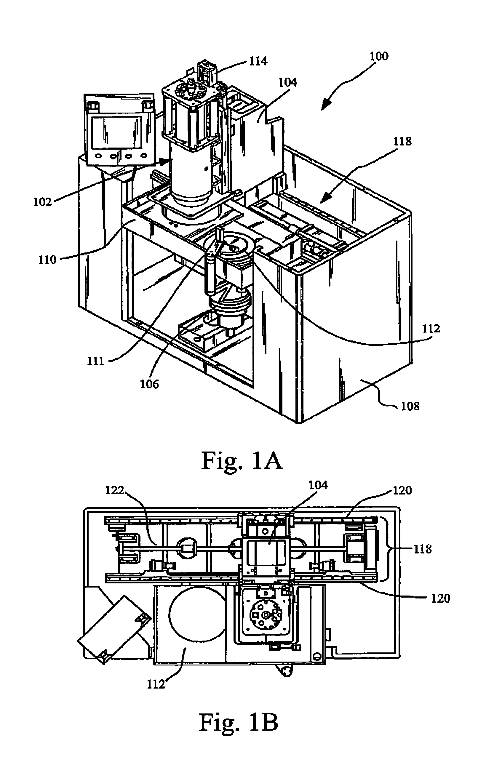
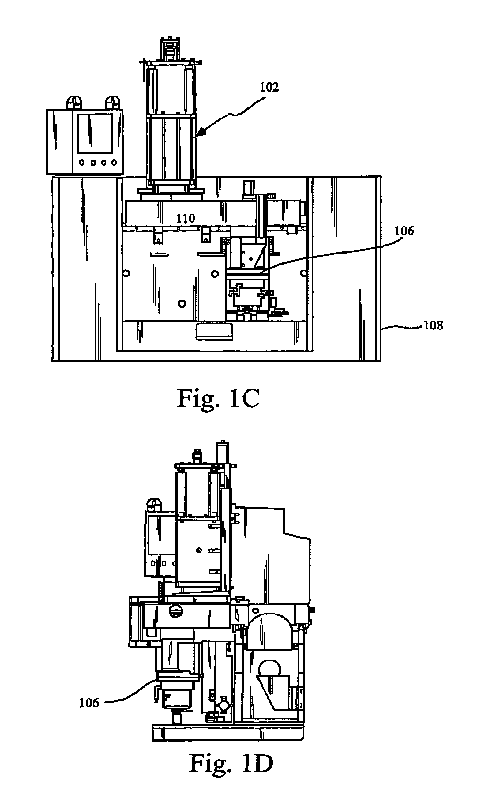
[0037]Referring first to FIGS. 1A, 1B, 1C and 1D shown are perspective, plan, front and side views respectively of one embodiment of a compact grinder assembly 100 in accordance with one embodiment of the present invention. Shown is a grind spindle 102, a spindle support column 104, a work spindle 106, a cabinet 108, a splash pan 110, a chuck 112, a thickness probe 111, a ball screw assembly 114, a bed portion 118, rails 120 and a ball screw 122.

[0038]The grind spindle 102 is coupled with the spindle support column 104, and the spindle support column 104 is engaged with the rails 120 and the ball screw 122. The cabinet 108 supports the rails 120, ball screw 122, the work spindle 106 and the splash pan 110. The thickness probe 111 is coupled with th...


PUM

PropertyMeasurementUnit
Forceaaaaaaaaaa
Pressureaaaaaaaaaa
Feed rateaaaaaaaaaa

Abstract

A grinding assembly for shaping work pieces that includes one or more grind spindles. Each of the grind spindles include two independent grinding wheels driven by a single spindle drive. The grind spindles translate horizontally to perform both edge and face grinding with a single grind spindle. A non-contact position sensor in a work spindle measures work spindle displacement during grinding and provides feedback to the grind spindle to regulate the force imparted on the work piece by the grind spindle. In variations, an abrasive wheel disposed radially with respect to an axis of spindle rotation is utilized to perform edge grinding of the work piece. In other variations cleaning, polishing and grinding are carried out in a single grinding assembly. In yet other variations, a wheel dressing apparatus is utilized to dress the wheel when one or more forces to maintain productivity of the grind wheel exceed a threhold.

Description

BACKGROUND OF THE INVENTION[0001]1. Field of the Invention[0002]The present invention relates generally to material processing, and more specifically to grinding technologies. Even more specifically, the present invention relates to surface and edge grinding technologies.[0003]2. Discussion of the Related Art[0004]The use of the semiconductor devices in today's commercial goods is undergoing dramatic growth. In order to expand the use of semiconductor devices in lower cost traditional products, semiconductor devices must be produced at previously unattainable low cost and with smaller size active devices and smaller line widths. Virtually every step of semiconductor device production is undergoing extensive investigation in an effort to obtain efficiencies and cost savings that will expand the market for semiconductor products.[0005]Among the newer methods is the use of “Silicon on Insulator” and other bonding techniques where multiple silicon or other materials are bonded together ...

Claims


Application Information

Patent Timeline
IPC IPC(8): B24B49/00B24B1/00B24B7/00B24B21/18B24B7/22B24B49/16
CPCB24B7/22B24B49/16
Inventor WALSH, THOMAS A.KASSIR, SALMAN MOUDREK
Owner REVASUM INC
Why Eureka
Try Eureka