
Modular CPU enclosure for gaming machines

a gaming machine and module technology, applied in the field of gaming machines, can solve the problems of pin/connector damage, difficulty in routine maintenance, and difficulty in insertion and removal of the cpu tray, and achieve the effect of convenient insertion and disassembly

Inactive Publication Date: 2006-10-10
IGT
View PDF33 Cites 29 Cited by
  • Summary
  • Abstract
  • Description
  • Claims
  • Application Information

AI Technical Summary

Benefits of technology

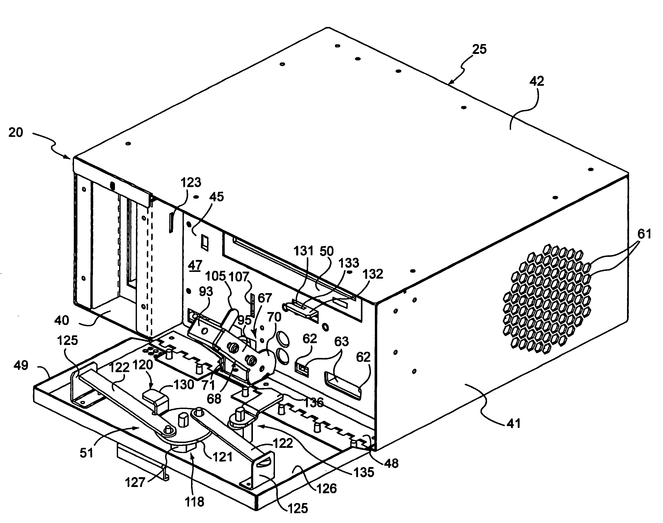
[0013]The release device includes a cam portion interengaged between the modular enclosure and the housing to facilitate insertion and disengagement of the second electrical connector into and from the first electrical connector. The cam portion further aids movement of the modular enclosure toward the mounting condition as the release device is moved toward the first position and, aids movement of the modular enclosure toward the removal condition as the release device is moved toward the second position.
[0014]In another aspect of the present invention, a removable processor enclosure apparatus is provided for use in a gaming machine, which includes an enclosure securably containing the CPU electrical components in an interior space thereof. The enclosure is adapted for sliding receipt in the interior portion of the gaming machine housing between a mounting condition, mounting the enclosure to the housing and electrically coupling a second electrical connector of the enclosure to the first electrical connector of the housing, and a removal condition, enabling removal of the enclosure from the housing. The enclosure further includes a door movably mounted between an open position and a closed position. In the opened position, access is allowed to the interior space, while in the closed position, access is prevented to the interior space. A lock mechanism cooperates between the door and the enclosure to prevent movement of the door from the closed position to the open position.

Problems solved by technology

One problem associated with this design, however, is that the forces required to simultaneously connect and disconnect these connectors can be substantial.
Insertion and removal of the CPU tray, consequently, may be difficult during routine maintenance.
In some instances, the pins / connectors may be damaged (e.g., bent) during forced manipulation, while in other instances injuries may occur during tray insertion and removal.
Another problem associated with this design is that the CPU tray may be inadvertently removed while the motherboard and the CPU are still powered.
Known as hot swapping, in some cases, arcing can occur between the powered connectors which can damage the contacts and / or pins.
In the worst case scenario, a fire or a significant amount of internal component damage can occur.

Method used


Image

  • Modular CPU enclosure for gaming machines
  • Modular CPU enclosure for gaming machines
  • Modular CPU enclosure for gaming machines

Examples


Embodiment Construction

[0032]While the present invention will be described with reference to a few specific embodiments, the description is illustrative of the invention and is not to be construed as limiting the invention. Various modifications to the present invention can be made to the preferred embodiments by those skilled in the art without departing from the true spirit and scope of the invention as defined by the appended claims. It will be noted here that for a better understanding, like components are designated by like reference numerals throughout the various Figures.

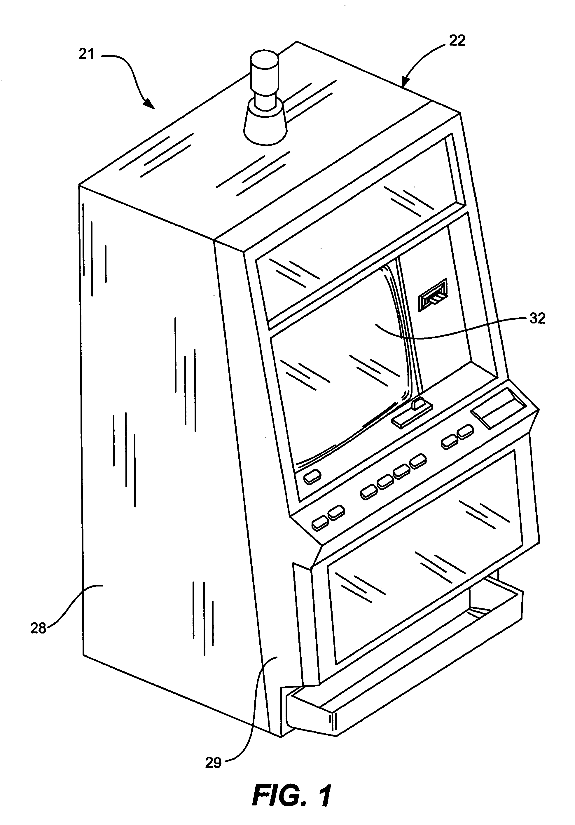
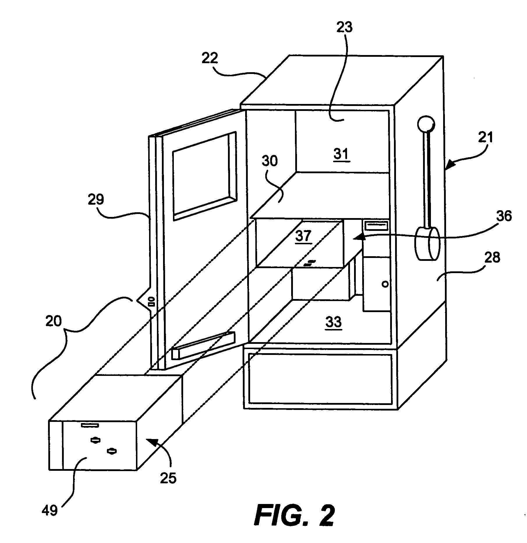
[0033]Attention is now directed to FIGS. 1–7 where the present invention modular enclosure apparatus, generally designated 20, is illustrated for use in a video gaming machine 21. These conventional gaming machines include a housing 22 defining an interior portion 23 therein, and a first electrical connector 26 disposed in the interior portion 23. A Central Processing Unit (CPU) enclosure, generally designated 25, is provided secur...


PUM


Abstract

A removable processor enclosure apparatus for use in a gaming machine having a housing defining an interior portion, and a first electrical connector disposed in the interior portion. The enclosure apparatus includes an enclosure containing the CPU electrical components therein, and is adapted for sliding receipt in the interior portion of the gaming machine housing between a mounting condition and a removal condition. In the mounting condition, the enclosure is mounted to the housing and electrically coupling a second electrical connector of the enclosure to the first electrical connector of the housing. In the removal condition, the enclosure can be removed from the housing. A release device is interengaged between the housing and the enclosure, and is selectively movable between a first position, locking the enclosure in the mounting condition, and a second position, releasing the enclosure from the mounting condition to the removal condition and disconnecting the second electrical connector from the first electrical connector.

Description

CROSS REFERENCE TO RELATED APPLICATIONS[0001]This application is a divisional of and claims priority to U.S. patent application Ser. No. 09 / 687,243 entitled “MODULAR CPU ENCLOSURE FOR GAMING MACHINES,” filed on Oct. 13, 2000, and now issued as U.S. Pat. No. 6.699,128, which is incorporated by reference herein for all purposes.BACKGROUND OF THE INVENTION[0002]1. Field of Invention[0003]The present invention relates to gaming machines such as slot machines or video poker machines. More particularly, the present invention relates to enclosures applied to protect the primary electrical components operating the gaming machines.[0004]2. Description of the Prior Art[0005]As technology in the gaming industry progresses, the once traditional mechanically-driven reel slot machines have been replaced with electronic counterparts having CRT video displays or the like. These video / electronic gaming advancements enable the operation of more complex gambling games, which would not otherwise be pos...

Claims


Application Information

Patent Timeline
Patent Type & Authority Patents(United States)
IPC IPC(8): A63F9/24G07F17/32H05K5/02
CPCG07F17/32G07F17/3216H05K5/0256Y10T292/0956Y10T292/1089
Inventor BEADELL, JOHN LEAGHSTOCKDALE, JAMES W.
Owner IGT
Learn More