
Device for concealing caulking joint and method

a caulking joint and device technology, applied in the direction of rod connections, building components, applications, etc., can solve the problems of affecting the appearance of caulking joints

Active Publication Date: 2006-10-10
RCR INT
View PDF9 Cites 19 Cited by
  • Summary
  • Abstract
  • Description
  • Claims
  • Application Information

AI Technical Summary

Benefits of technology

[0007]It is an aim of the present invention to provide a device that can conceal an existing caulking joint between two adjacent surfaces.
[0008]It is another aim of the present invention that the device forms a watertight joint to prevent water infiltration between the surfaces and the device.
[0009]It is another aim of the present invention that the device be relatively easy and quick to install over the existing caulking joint.
[0010]It is yet another aim of the present invention to provide a method for concealing a joint between adjacent surfaces that does not involve the removal of the existing caulking.

Problems solved by technology

Over time, the high humidity level in the bathroom can stimulate the growth of mildew on the caulking joints.
Also, these joints can be damaged.
While these devices isolate the joint from water exposure and resist deterioration better than a caulking joint, their installation requires the removal of the existing caulking, a process that can be very difficult and time consuming.
Unfortunately, this device also requires the removal of the existing caulking before installation in order to be able to apply a fresh caulking joint.
These finishing strips are however limited to drywalls, as they are either too rigid to adequately conform to irregular wall and bathtub surfaces or include a plurality of slits making them unsuitable for use in a bathroom joint.

Method used


Image

  • Device for concealing caulking joint and method
  • Device for concealing caulking joint and method
  • Device for concealing caulking joint and method

Examples


Embodiment Construction

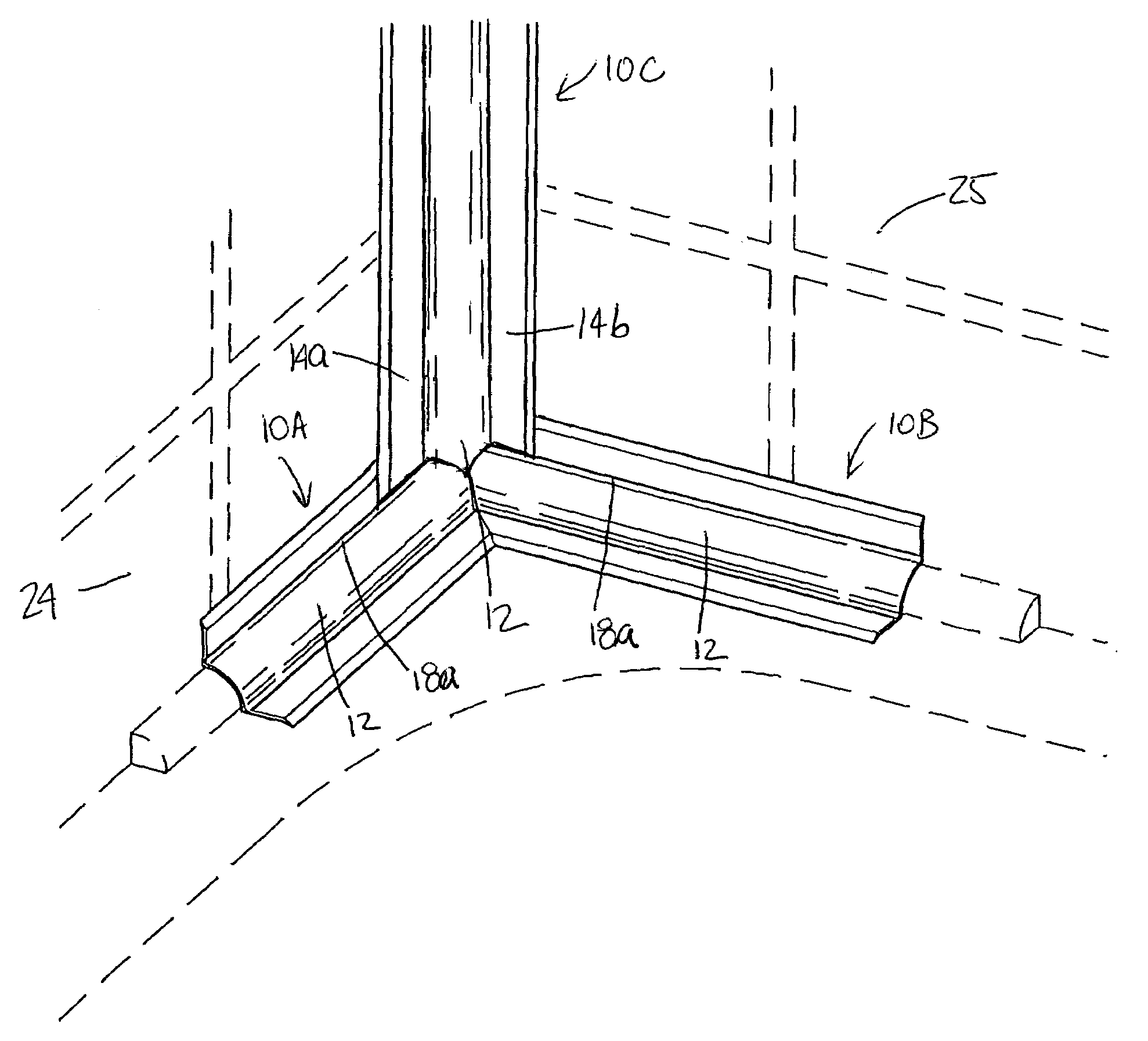
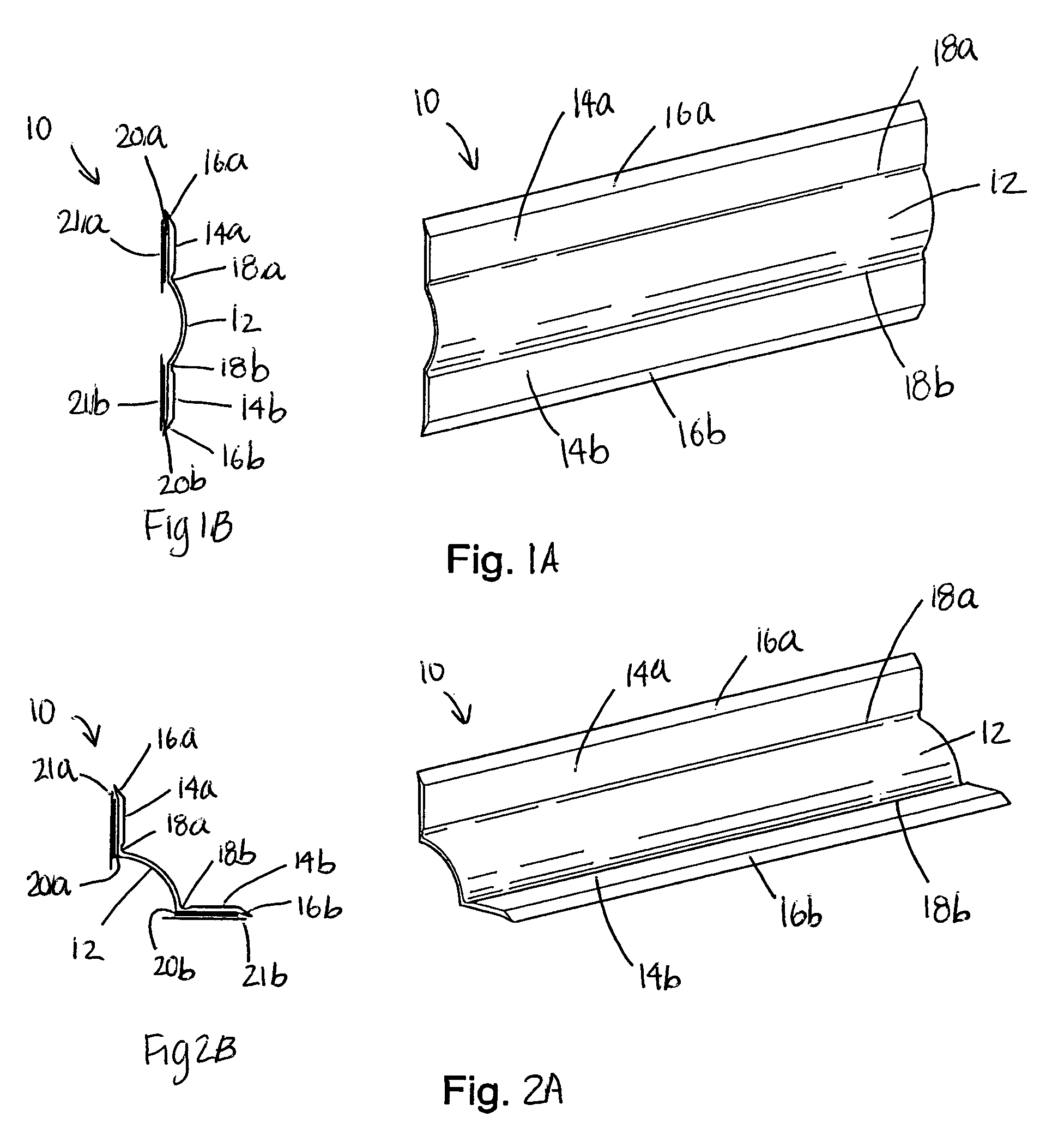
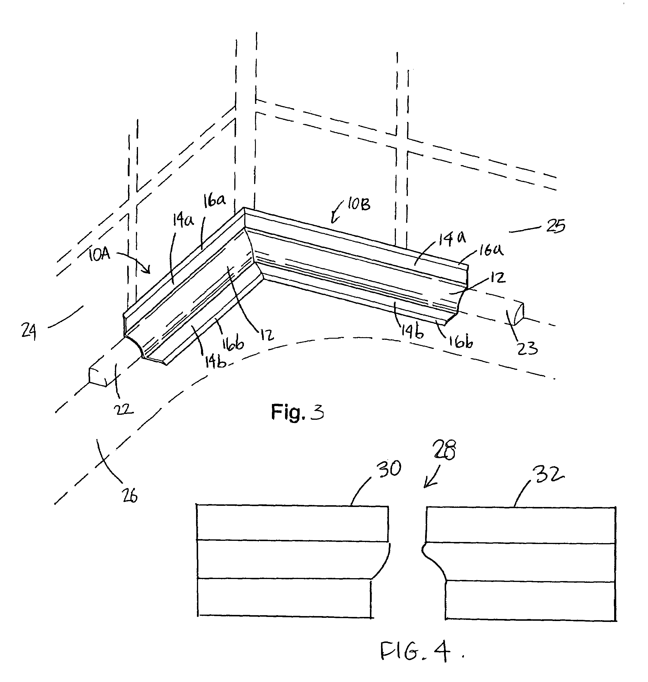
[0022]A preferred embodiment of the present invention is shown in FIG. 1A to 2B and will now be described. A device generally shown at 10 is composed of a transversally convex elongated central strip 12 linking two flaps 14a,b. Each of the flaps 14a,b is terminated by a tapered edge 16a,b slightly inclined towards a back side thereof. The flaps 14a,b are connected to the central strip 12 through hinge joints 18a,b. Each joint 18a,b acts as a hinge to allow easy folding of the flaps 14a,b from a flat configuration illustrated in FIG. 1A–1B to an installation configuration illustrated in FIG. 2A–2B. An adhesive strip 20a,b is preferably installed on the back side of each flap 14a,b. A backing strip 21a,b protects the exposed side of each adhesive strip 20a,b.

[0023]In order to protect the covered caulking joint from water infiltration, the device must be made of a water-resisting and watertight material. In a preferred embodiment, the device is made of a flexible water-resisting and w...


PUM

PropertyMeasurementUnit
flexibleaaaaaaaaaa
degree of flexibilityaaaaaaaaaa
adhesiveaaaaaaaaaa

Abstract

A device for concealing a caulking joint formed between adjacent first and second surfaces comprising an elongated central strip having first and second edges and the strip having first and second sides; a first flap longitudinally connected to the elongated central strip along the first edge, the first flap having a first side adapted to be adhered to a first of the adjacent surfaces such that the first flap conforms to the first of the adjacent surfaces in a watertight manner; a second flap longitudinally connected to the elongated central strip along the second edge, the second flap having a first side adapted to be adhered to a second of the adjacent surfaces such that the second flap conforms to the second of the adjacent surfaces in a watertight manner; and the central strip being adapted to cover the caulking joint with the first side of the central strip facing the caulking joint when the first flap is adhered to the first surface and the second flap is adhered to the second surface, whereby the caulking joint is concealed by the device.

Description

FIELD OF THE INVENTION[0001]The present invention relates to a device for concealing the caulking joint or the like between adjoining surfaces. More specifically, the present invention is directed to a device concealing the caulking joints typically found in the water rooms of households.BACKGROUND OF THE INVENTION[0002]In a bathroom, joints need to be properly sealed against water infiltration, for example the joints between a tile wall and an adjoining bathtub or the joint between a similar wall and a counter. These joints are usually sealed using a caulking compound such as silicone or latex based products. Over time, the high humidity level in the bathroom can stimulate the growth of mildew on the caulking joints. Also, these joints can be damaged.[0003]To improve the appearance of these joints, a number of moldings have been introduced to replace caulking. Such devices as taught by U.S. Pat. No. 4,706,427, issued on Nov. 17, 1987 to Zeilinger, are often rigid and are designed t...

Claims


Application Information

Patent Timeline
Patent Type & Authority Patents(United States)
IPC IPC(8): B32B9/00A47K3/00
CPCA47K3/008Y10T428/14Y10T428/1486Y10T428/24777Y10T428/24793Y10T403/4602Y10T428/2419Y10T428/24628
Inventor MARTEL, GAETAN
Owner RCR INT
Learn More