Strobe light and laser beam detection for laser receiver

a laser receiver and laser beam technology, applied in the field of equipment, can solve the problems of difficult detection of light and not always being completely effectiv

Active Publication Date: 2006-10-10
TRIMBLE NAVIGATION LTD
View PDF7 Cites 37 Cited by
  • Summary
  • Abstract
  • Description
  • Claims
  • Application Information

AI Technical Summary

Benefits of technology

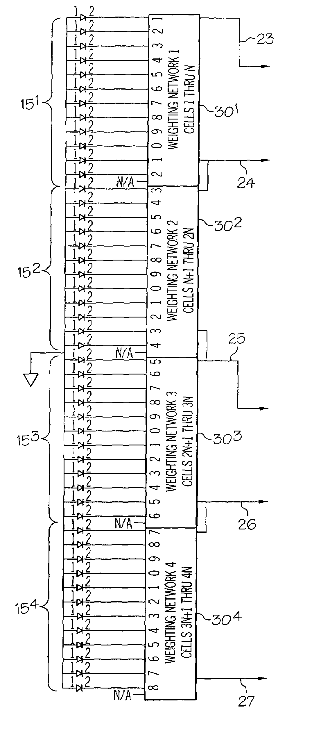
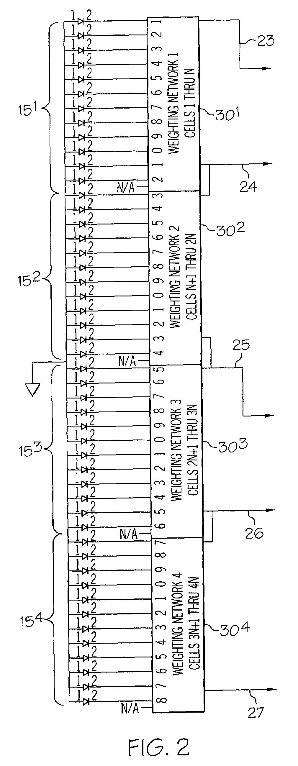
[0010]Accordingly, it is an object of the present invention to provide a device and method for detecting the relative position of reference light; to provide such a device and method in which a plurality of photodetector arrays are positioned such that the photodetector elements in all of the arrays are arranged in an extended row; and to provide such a device and method in which a plurality of weighting circuits are responsive to the arrays and a plurality of output circuits are responsive to the weighting circuits for determining the position of the reference light, and for determining whether the device is illuminated by a laser beam or by a strobe light pulse.

Problems solved by technology

This may not always be completely effective, however, and in addition to the unwanted interference, the optical filters may also attenuate light at the frequencies of interest, making such light harder to detect.

Method used


Image

  • Strobe light and laser beam detection for laser receiver
  • Strobe light and laser beam detection for laser receiver
  • Strobe light and laser beam detection for laser receiver

Examples


Embodiment Construction

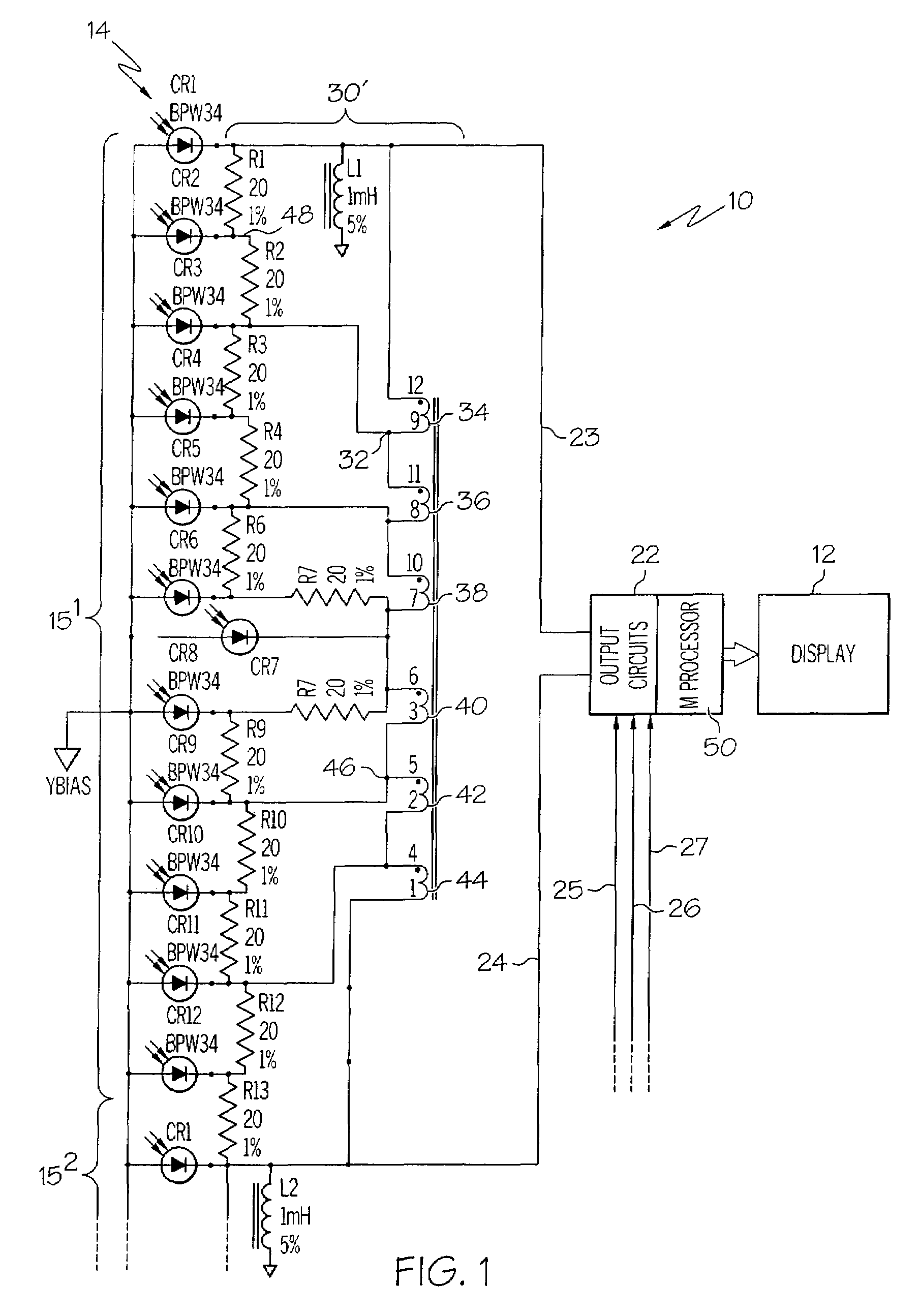
[0016]Reference is made to FIG. 1, which generally illustrates a portion of a detection device 10 according to the present invention. The device detects reference light, such as laser light, and provides an indication of the location of the reference light with respect to the device. The device may also detect reference strobe pulses, as well. Reference light may, for example, be produced by laser transmitters as shown in U.S. Pat. No. 4,062,634, issued Dec. 13, 1977, to Rando et al, or in U.S. Pat. No. 4,732,471, issued Mar. 22, 1988, to Cain et al. Other light transmitters may also be used.

[0017]The detector device 10 includes a display 12, and a photodetector arrangement 14 including a plurality of photodetector arrays 151, 152, 153, and 154, shown in FIG. 2, arranged in a generally vertical row. Although for purposes of FIGS. 1 and 2 four photodetector arrays are shown, a greater or lesser number may be positioned in an extended row to permit light detection over a larger or les...


PUM


Abstract

A device and method detect a moving, relatively thin beam of laser light, and distinguishing between illumination of photodetectors by the beam, and illumination of the photodetectors by an omnidirectional pulse of light. A plurality of photodetector arrays are arranged in a generally vertical row, with each array having a generally vertical row of photodetector elements. Weighting circuits associated with the arrays provide first and second reference signals for each array related to the elements illuminated in the array. The ratio of sum of the reference signals to the difference between the largest and smallest of the reference signals is determined and interpreted as indicating illumination by a relatively thin beam of laser light when the ratio is less than a predetermined level, and as indicating illumination by an omnidirectional pulse of light when the ratio is greater than the predetermined level.

Description

CROSS-REFERENCE TO RELATED APPLICATIONS[0001]Not applicable.STATEMENT REGARDING FEDERALLY SPONSORED RESEARCH OR DEVELOPMENT[0002]Not Applicable.BACKGROUND OF THE INVENTION[0003]The present invention relates to equipment of the type used in surveying and construction and, more particularly, to a detector device for such applications which has an improved photodetector arrangement for detecting the position of reference light. The light may typically be a rotating laser beam that defines a reference plane of light or a stationary reference plane or cone of laser light. The reference plane may be horizontal or inclined, as dictated by the application. Additionally, a transmitter projecting the reference light may also regularly project a strobe light in synchronization with rotation of the beam so that the beam defines a specific azimuth angle.[0004]Laser systems have commonly been employed in surveying and construction in which a laser beam is rotated in either a horizontal or a grade...

Claims


Application Information

Patent Timeline
Patent Type & Authority Patents(United States)
IPC IPC(8): G01C21/02
CPCG01C15/006
Inventor GREEN, FRANCISCO ROBERTODOUGLAS, FRANK BEARD
Owner TRIMBLE NAVIGATION LTD
Why Eureka
Try Eureka