Circuit designs and control techniques for high frequency electronic ballasts for high intensity discharge lamps

a technology of electronic ballast and high intensity, which is applied in the direction of electric variable regulation, process and machine control, instruments, etc., can solve the problems of difficult to identify whether the ballast circuit output is short-circuited or the lamp in normal operation, and the discharge arc current is not sufficient, so as to accelerate the warming of the lamp plasma

Inactive Publication Date: 2006-10-10
CITY UNIVERSITY OF HONG KONG
View PDF30 Cites 37 Cited by
  • Summary
  • Abstract
  • Description
  • Claims
  • Application Information

AI Technical Summary

Benefits of technology

[0022]Preferably the ballast further comprises means for maintaining the lamp current at a level higher than its

Problems solved by technology

The situation is particularly serious if a long cable is used to connect the lamp and the ballast, because long cables have relatively large inductance that will limit the rate of change of current di/dt.
Because of the above transition characteristics, it is difficult to identify whether the ballast circuit output is short-circuited or the lamp in normal operation.
Many previous ballasts did not provide sufficient discharge arc current from the ballast to maintain the arc just after starting.
If the initial discharge current is not sufficient, the lamp will try to turn on but the arc will turn off quickly because of insufficient energy to sustain the arc in the arc tube.
This often results in lamp flickering and/or unreliable lamp operation.
The major limitation of this circuit is the use of a large L2.
In the worst case, the arc may not be established

Method used


Image

  • Circuit designs and control techniques for high frequency electronic ballasts for high intensity discharge lamps
  • Circuit designs and control techniques for high frequency electronic ballasts for high intensity discharge lamps
  • Circuit designs and control techniques for high frequency electronic ballasts for high intensity discharge lamps

Examples


Embodiment Construction

A. Circuit Schematic of a Ballast for a High Intensity Discharge Lamp

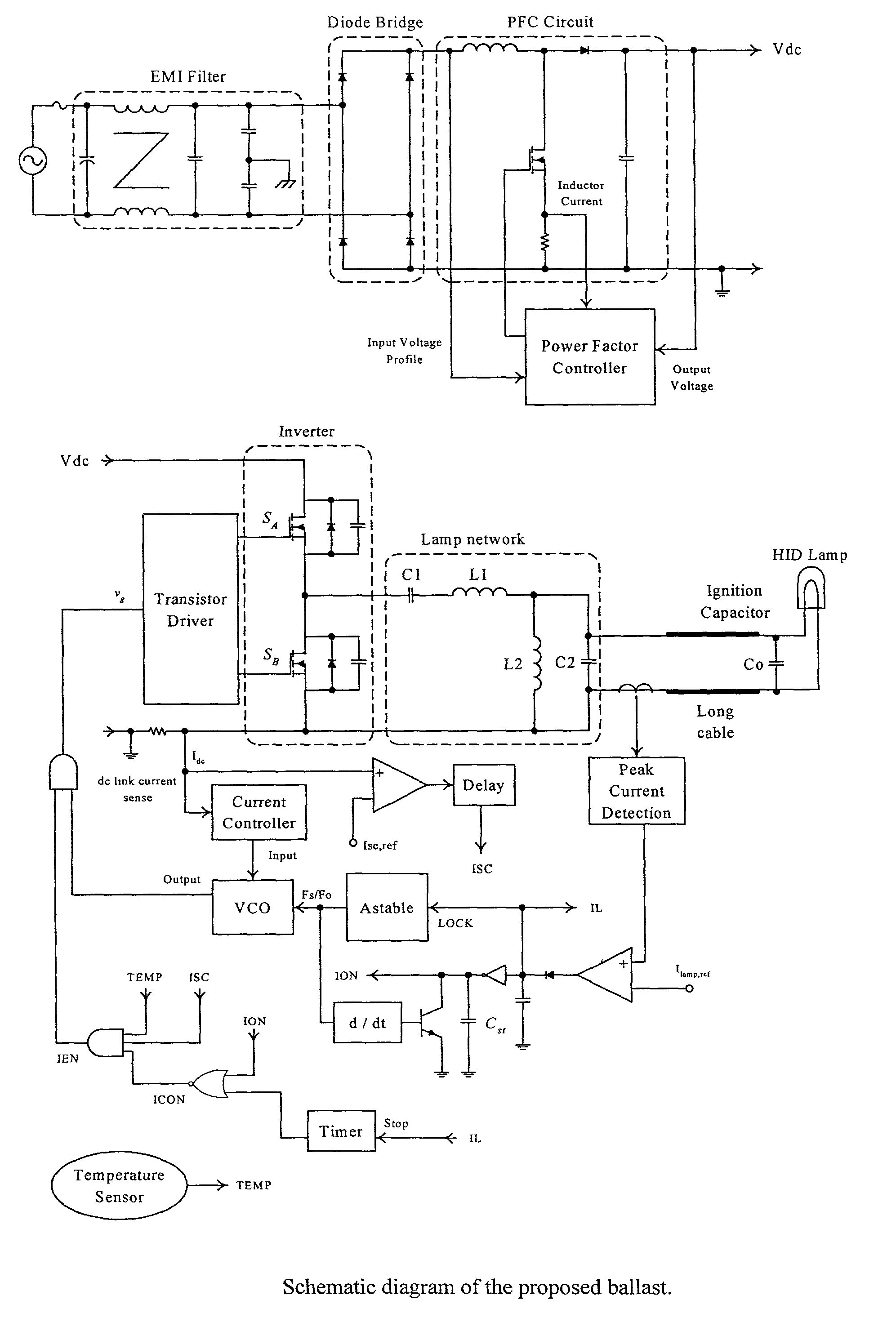
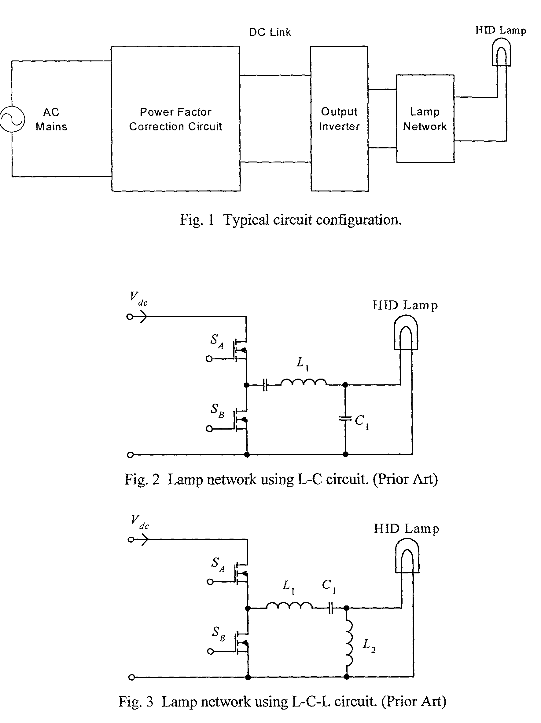
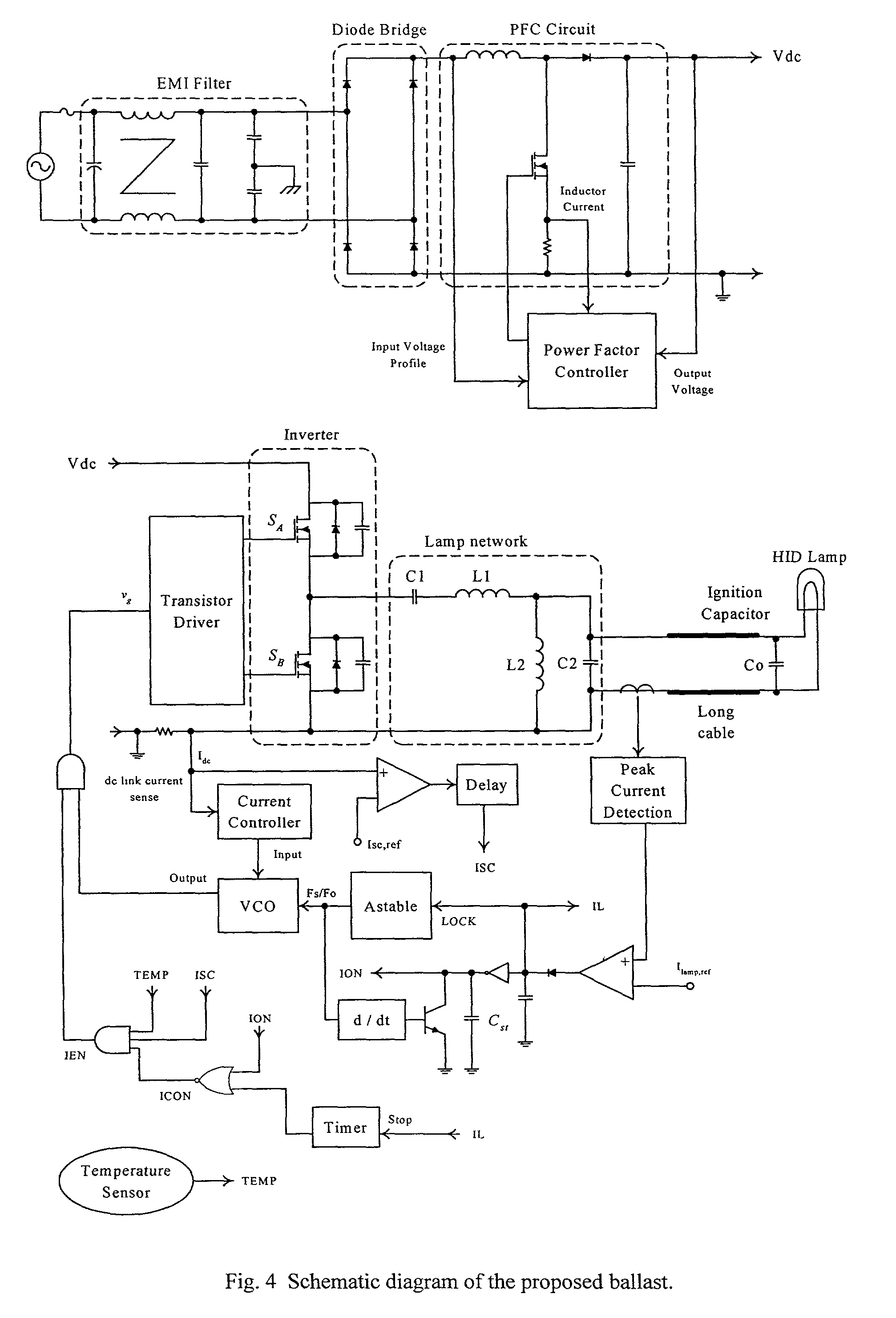
[0032]A circuit schematic of an electronic ballast according to a preferred embodiment of the invention is shown in FIG. 4. The power circuit consists of the following components:[0033]1. Electromagnetic interference (EMI) filter—This is used to suppress the noise, that is generated by the ballast, from getting into the supply mains.[0034]2. Diode bridge—This is a full-wave rectifier and its major function is to rectify the ac mains voltage into a dc voltage.[0035]3. Power factor correction (PFC) circuit—The major function of the PFC circuit is to shape the input current waveform sinusoidally and to keep the input current in phase with the input voltage. The most common circuit topology for the PFC is a boost type dc power converter. This ensures that the input current of the boost converter follows the rectified input voltage. Moreover, a stable dc voltage Vdc is regulated at the output. In this circuit example, t...


PUM


Abstract

The present invention provides an electronic ballast for a high intensity discharge lamp such as a metal halide lamp. The ballast includes an inverter and a resonant circuit with an ignition capacitor between the resonant circuit and the lamp. The ignition capacitor serves to provide the necessary start-up energy and also serves to provide a low impedance discharge path. A single ignition capacitor may be sufficient, but if a long cable is used to connect the lamp to the ballast, then two ignition capacitors in parallel at opposite ends of the cable may be used. The ballast further provides means for monitoring and controlling lamp power by monitoring a nominally constant dc link voltage, and means for detecting short-circuit and open circuit conditions. A retrial mechanism is provided in the event of the lamp failing to ignite that includes a temporary disabling of the inverter in order to keep the rms lamp voltage low.

Description

[0001]This application is a non-provisional filing based on U.S. Provisional Application Ser. No. 60 / 263,737, filed 24 Jan. 2001.FIELD OF THE INVENTION[0002]This invention relates to novel circuit designs and control techniques for high frequency (from 20 kHz to 1 MHz) electronic ballasts for high-intensity-discharge (HID) lamps, such as metal-halide lamps, to ensure successful startup of lamps and to provide circuit protection. The present invention relates in particular, though not exclusively, to ballasts that are suitable for discharge lamp system in which the HID lamp is connected to the ballast circuit via long cable.BACKGROUND OF THE INVENTION[0003]Among various light sources, high-density-discharge (HID) lamps exhibit the best combination of the high luminous efficacy and good color rendition with the high power compact source characteristics. HID lamps have been used in many applications, such as wide area floodlighting, stage, studio, and entertainment lighting to UV lamps...

Claims


Application Information

Patent Timeline
IPC IPC(8): H05B37/02H05B41/24H05B41/282H05B41/288H05B41/292H05B41/38H05B41/392
CPCH05B41/2881H05B41/2883H05B41/2886H05B41/2921H05B41/2925H05B41/386H05B41/388H05B41/392Y02B20/204Y02B20/208Y02B20/00
Inventor HUI, SHU YUEN RONCHUNG, SHU-HUNG
Owner CITY UNIVERSITY OF HONG KONG
Why Eureka
Try Eureka