Circuit arrangement
a circuit arrangement and circuit technology, applied in the field of circuit arrangement, can solve problems such as the change in the received amplitude at the receiver end, and achieve the effect of safe identification of the level change and easy identification
- Summary
- Abstract
- Description
- Claims
- Application Information
AI Technical Summary
Benefits of technology
Problems solved by technology
Method used
Image
Examples
Embodiment Construction
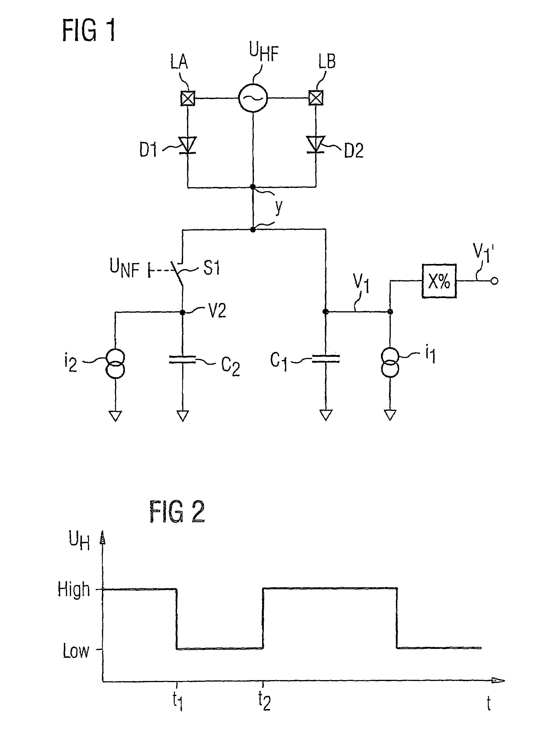
[0018]In the case of the first inventive exemplary embodiment shown in FIG. 1, a radio-frequency input voltage UHF is applied to the input of the demodulator circuit, denoted by the two input connections LA and LB. FIG. 2 shows the envelope of the absolute amplitude value of the radio-frequency input voltage over time. As can be seen, it alternates between a high amplitude level, denoted by “high”, and a low amplitude level, denoted by “low”. This rectified radio-frequency input voltage UHF is thus present on the node Y in rectified form. The node Y has two charging circuits connected to it in parallel which are charged by the rectified radio-frequency voltage.
[0019]The first charging circuit comprises the capacitor C1 and a current source i1, which are again connected in parallel starting from the voltage node V1. Correspondingly, the second charging circuit is made up of the capacitor C2 and the current source i2, which are connected in parallel starting from the voltage node V2. ...
PUM
 Abstract
Description
Claims
Application Information
 - R&D
- Intellectual Property
- Life Sciences
- Materials
- Tech Scout
- Unparalleled Data Quality
- Higher Quality Content
- 60% Fewer Hallucinations
Browse by: Latest US Patents, China's latest patents, Technical Efficacy Thesaurus, Application Domain, Technology Topic, Popular Technical Reports.
© 2025 PatSnap. All rights reserved.Legal|Privacy policy|Modern Slavery Act Transparency Statement|Sitemap|About US| Contact US: help@patsnap.com


