Circuit arrangement

a circuit arrangement and circuit technology, applied in the field of circuit arrangement, can solve problems such as the change in the received amplitude at the receiver end, and achieve the effect of safe identification of the level change and easy identification

Active Publication Date: 2005-10-06
INFINEON TECH AG
View PDF3 Cites 2 Cited by
  • Summary
  • Abstract
  • Description
  • Claims
  • Application Information

AI Technical Summary

Benefits of technology

[0007] The invention is thus based on an object of providing an analog / digital converter circuit which safely identifies the level change between two states in the case of ASK modulations with as little involvement as possible.
[0008] The inventive circuit has the advantage that the change in the modulation level can easily be identified when the two charging voltages are compared.

Problems solved by technology

The problem of ASK modulation can be seen in that a change in the distance between the transmitter and the receiver of the signal modulated in this manner while the amplitude of the transmitted signal remains the same also results in a change in the received amplitude at the receiver end when the distance is altered.

Method used


Image

  • Circuit arrangement
  • Circuit arrangement
  • Circuit arrangement

Examples


Embodiment Construction

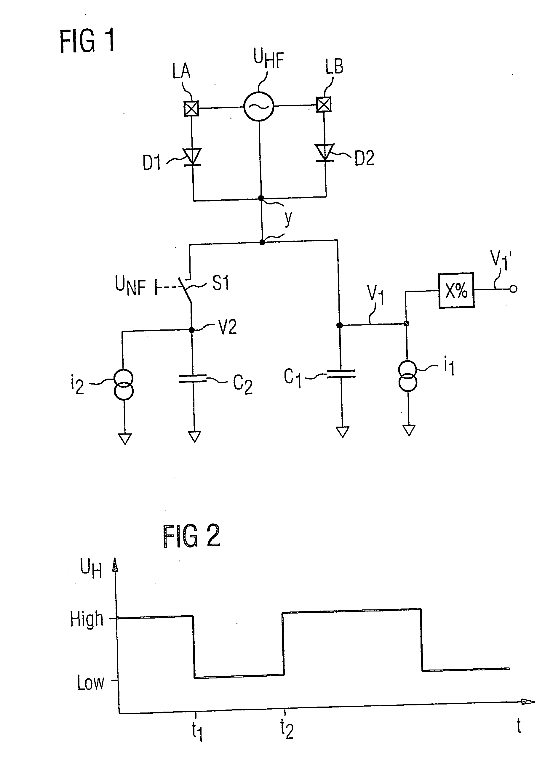
[0018] In the case of the first inventive exemplary embodiment shown in FIG. 1, a radio-frequency input voltage UHF is applied to the input of the demodulator circuit, denoted by the two input connections LA and LB. FIG. 2 shows the envelope of the absolute amplitude value of the radio-frequency input voltage over time. As can be seen, it alternates between a high amplitude level, denoted by “high”, and a low amplitude level, denoted by “low”. This rectified radio-frequency input voltage UHF is thus present on the node Y in rectified form. The node Y has two charging circuits connected to it in parallel which are charged by the rectified radio-frequency voltage.

[0019] The first charging circuit comprises the capacitor C1 and a current source i1, which are again connected in parallel starting from the voltage node V1. Correspondingly, the second charging circuit is made up of the capacitor C2 and the current source i2, which are connected in parallel starting from the voltage node V...


PUM


Abstract

Circuit arrangement for demodulating a voltage which is ASK modulated by alternating the amplitude between a low and a high level. Respective charging voltages are produced on first and second charging circuits, with a decoupling device decoupling the first charging circuit at a prescribed ratio between the charging voltage from the second charging circuit and an input voltage for a rectifier circuit.

Description

CROSS-REFERENCE TO RELATED APPLICATION [0001] This application is a continuation of International Patent Application Serial No. PCT / DE2003 / 003148, filed Sep. 22, 2003, which published in German on Apr. 29, 2004 as WO 2004 / 036860, and is incorporated herein by reference in its entirety.FIELD OF THE INVENTION [0002] The invention relates to a circuit arrangement for analog / digital conversion of a voltage which is (ASK) modulated by alternating the amplitudes between a low and a high level. BACKGROUND OF THE INVENTION [0003] When using contactless chip cards and the like, such as “contactless tags”, use is frequently made of “ASK modulation”. This is understood to be a radio-frequency signal which alternates between a first and a second level with data available in digital form and thus modulates the radio-frequency signal. [0004] In the same way as a distinction is made for digital data between “Yes” and “No” or “1” or “0” or “high” and “low”, a distinction is made between a high ampl...

Claims


Application Information

Patent Timeline
Patent Type & Authority Applications(United States)
IPC IPC(8): G06K19/07H03M1/00H03M1/50H04L25/06H04L27/06
CPCG06K19/0723H04L27/06H04L25/062
Inventor MISSONI, ALBERT
Owner INFINEON TECH AG
Why Eureka
Try Eureka