
Projection lens system and projector

a projection lens and projector technology, applied in the field of projection lens system of projectors, can solve the problems of drop in aberration performance, increase in cost of glass lens, and increase in effect, so as to suppress the effect of thermal deformation of aspherical lens on overall aberration-correcting performance, increase the cost incurred, and reduce the effect of thermal deformation

Inactive Publication Date: 2006-10-10
NITTO OPTICAL CO LTD
View PDF7 Cites 2 Cited by
  • Summary
  • Abstract
  • Description
  • Claims
  • Application Information

AI Technical Summary

Benefits of technology

The solution achieves superior image forming performance with reduced thermal deformation effects, allowing for stable high-quality image display in rear projectors, even in hot environments, without the need for additional aspherical lenses, thus maintaining low manufacturing costs.

Problems solved by technology

Aspherical lenses can be realized by glass lenses, but due to cost and the ease of machining, plastic lenses are often used.
However, since plastic lenses have a high coefficient of thermal expansion, changes in form due to heat conversely cause a drop in aberration performance.
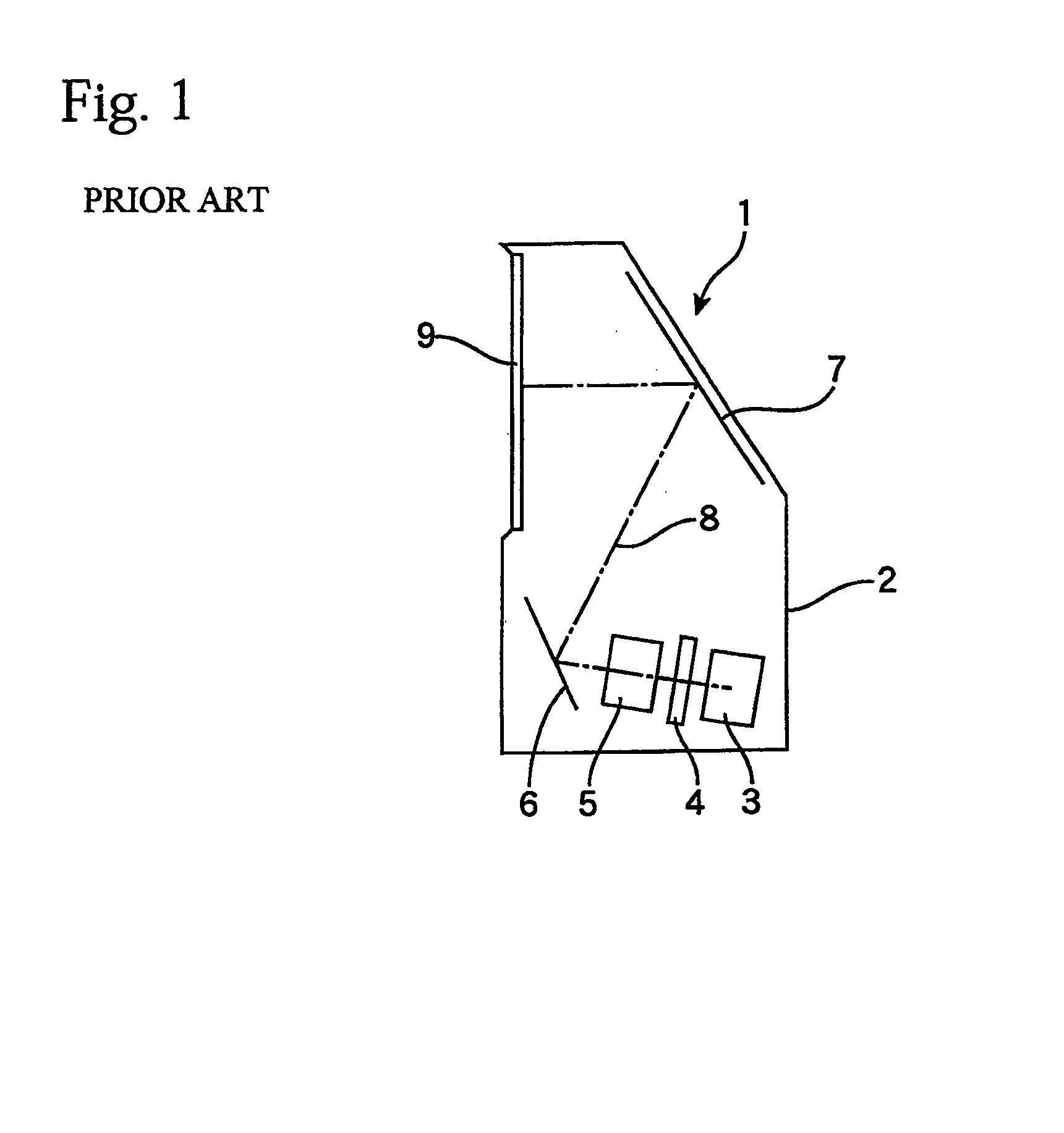
In particular, in a rear projector such as that shown in FIG. 1, a projection lens system is disposed in a completely closed environment and so is more susceptible to the effects of heat compared to a conventional projector system in which the screen and projector are separate and at least part of the lens system is exposed.
However, increasing the lens diameter of an aspherical lens has the demerits of a large increase in cost for a lens made of glass and of increased effects due to thermal deformation for a lens made of plastic.
Also, since a simple system is not expected to achieve a particularly high aberration correcting performance, the aspherical lens is only provided with a corrective performance such that thermal deformation of the aspherical lens will not have an especially large effect on the aberration performance of the entire lens system.
However, in the rear projectors that are currently being introduced, due to conditions relating to the placement of the lens system, the effect of heat is much greater than in a conventional projector.
In a method, such as that described in Japanese Laid-Open Patent Publication No. 2002-357769, that overcomes the effects of thermal deformation of aspherical lenses by increasing the number of aspherical lenses, the cost required to design and manufacture the aspherical lenses increases, and it is necessary to improve the design precision and raise the manufacturing yield so as to avoid a drop in the aberration performance due to thermal deformation of the additional aspherical lenses, which also results in high costs.

Method used


Image

  • Projection lens system and projector
  • Projection lens system and projector
  • Projection lens system and projector

Examples


first embodiment

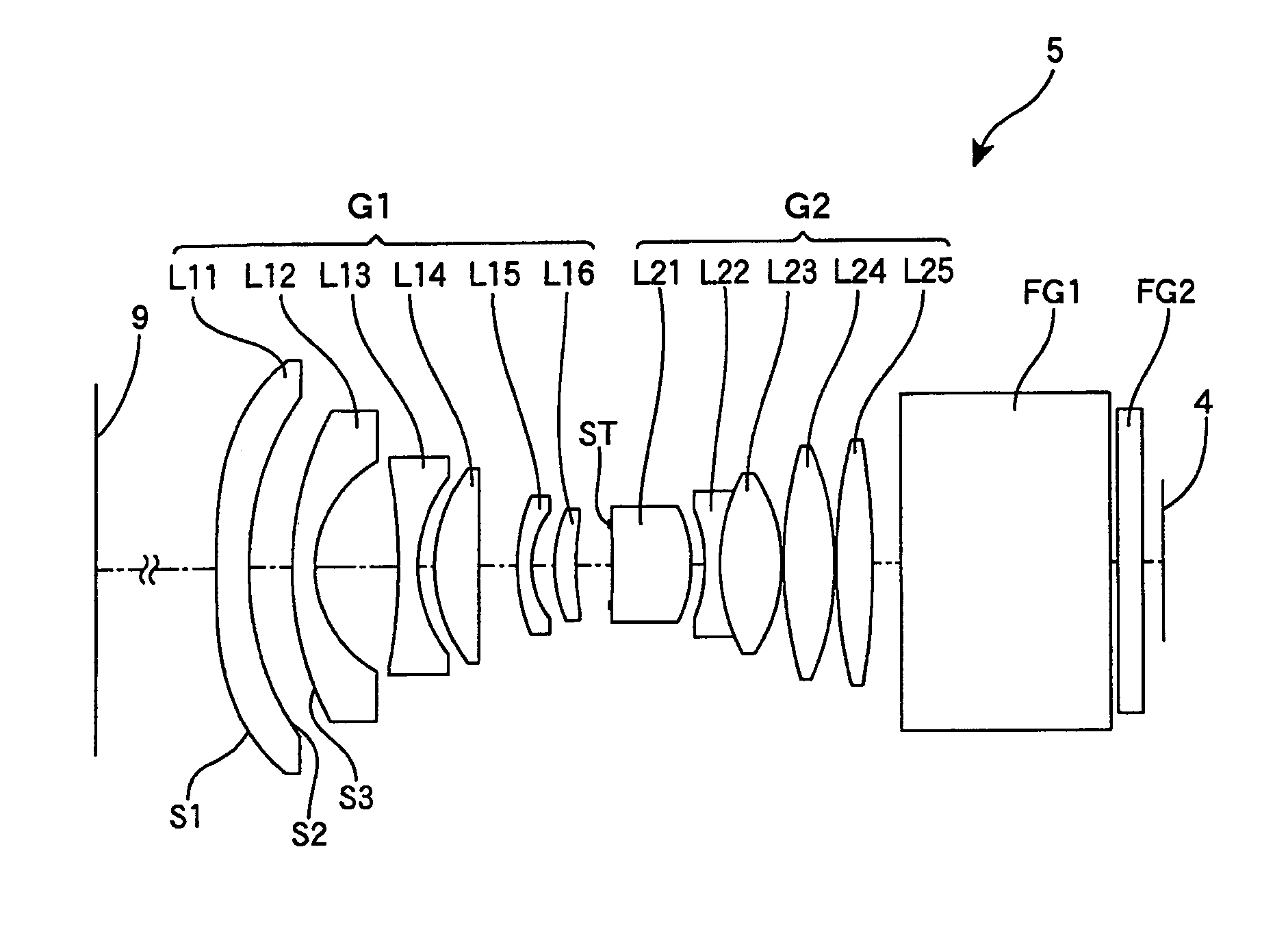
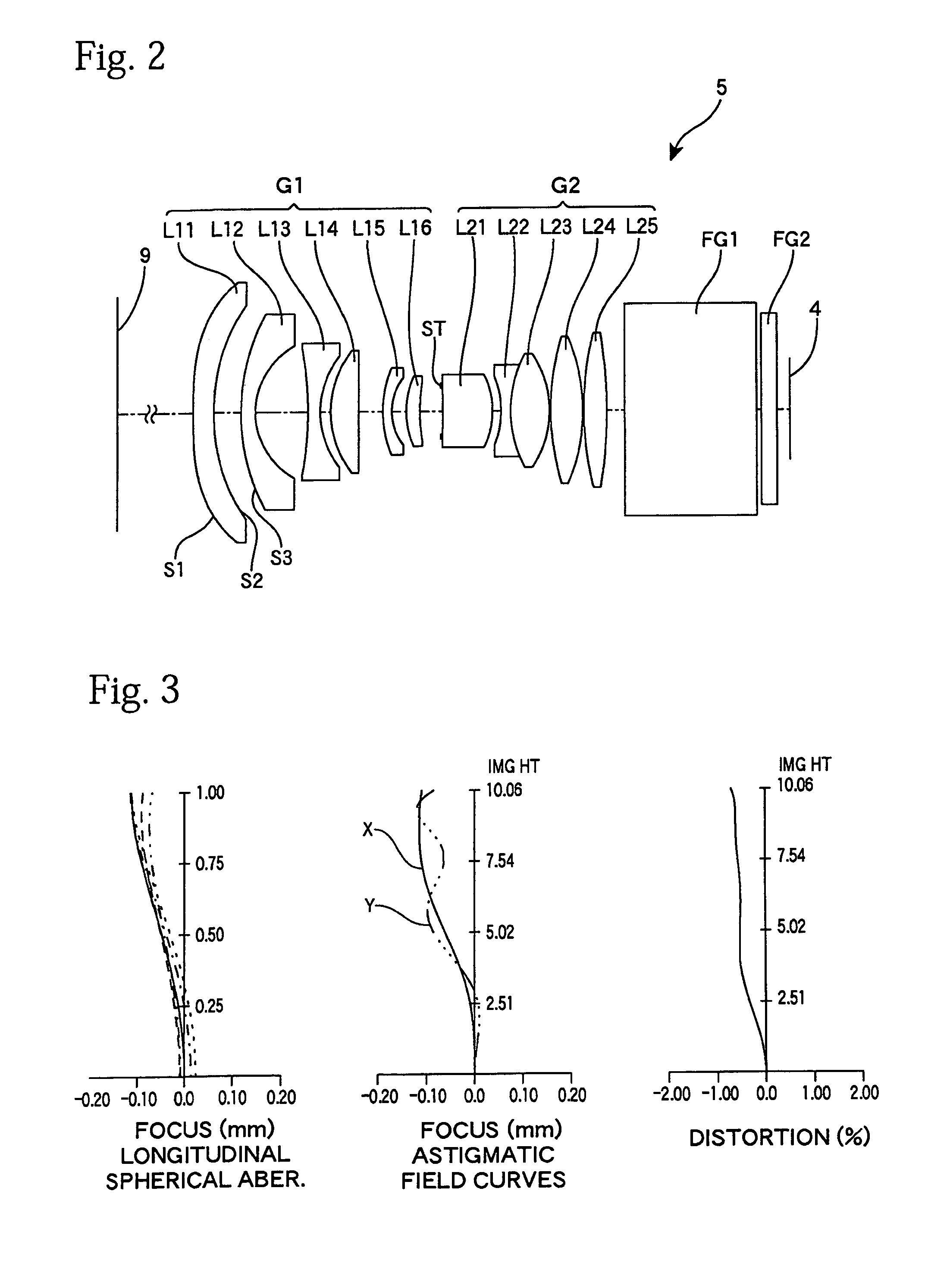
[0027]FIG. 2 shows the lens arrangement of a projection lens system 5 according to the present invention. The projection lens system 5 of the present embodiment is composed of eleven lenses L11 to L16 and L21 to L25 arranged in order from a screen 9 side (output side) toward a light valve 4 side (input side or incident side). These lenses L11 to L16 and L21 to L25 can be divided at a “stop” (aperture) ST into a former group G1 that has a negative overall refractive power and a latter group G2 that has a positive overall refractive power. Parallel glasses FG1 and FG2 disposed between the projection lens system 5 and the light valve 4 are optical low-pass filters.

[0028]The former group G1 is composed of six lenses that in order from the side of the screen 9 are negative meniscus lenses L11 and L12 that are convex on the screen side, a bi-concave negative lens L13, a convex lens L14 that is almost flat on the light valve side, a negative meniscus lens L15 that is convex on the screen s...

second embodiment

[0046]FIG. 4 shows the lens arrangement of a different projection lens system 5 according to the present invention. The projection lens system 5 according to the present embodiment is also composed of eleven lenses that are divided into two groups at the stop ST. From the screen 9 side, the former group G1 is composed of six lenses L11 to L16 and the latter group G2 is composed of five lenses L21 to L25. The fundamental shapes of these lenses L11 to L16 and L21 to L25 are the same as in the first embodiment, and therefore the projection lens system 5 of the present embodiment is also a lens system with an overall construction of eleven lenses that are negative, negative, negative, positive, negative, positive, positive, negative, positive, positive, and positive in order from the screen side. Detailed data on these lenses is given below.

Lens Data (No. 2)

[0047]

NoRDndνd181.4664.001.4918057.2lens L11237.0086.82335.5602.801.5891361.3lens L12416.2359.535456.8232.401.5891361.3lens L13620....


PUM


Abstract

A projection lens system that projects projection light from a light modulator onto a screen and which is telecentric on an input side is provided. The projection lens system comprises a first meniscus lens that is disposed closest to the screen, is convex on a screen side, and has negative refractive power; and a second meniscus lens that is disposed next closest to the screen, is convex on a screen side, and has negative refractive power. The first meniscus lens is made of plastic and at least one out of two curved surfaces thereof is aspherical, and a refractive power of the first meniscus lens is lower than a refractive power of the second meniscus lens. In the projection lens system, far superior aberration-correcting performance can be achieved and a drop in aberration-correcting performance due to thermal deformation can be prevented.

Description

BACKGROUND OF THE INVENTION[0001]1. Technical Field[0002]The present invention relates to a projection lens system of a projector that enlarges and projects an image displayed on a light valve, such as a liquid crystal panel or a DMD, onto a screen.[0003]2. Description of the Related Art[0004]Japanese Laid-Open Patent Publication No. 2002-357769 discloses the use of a pair of plastic aspherical lenses in a projection lens device used in a projector. In this publication, the aspherical lens of the front side has a negative power and the aspherical lens of the rear side has a positive power, so that when these lenses made of plastic deform due to heat and the refractive powers thereof change, the effects of such deformation are cancelled out by one lens having a positive power and the other lens having a negative power, which suppresses the drop in aberration-correcting performance.[0005]Aspherical lenses are often introduced into lens systems to correct aberration at a high level usi...

Claims


Application Information

Patent Timeline
Patent Type & Authority Patents(United States)
IPC IPC(8): G02B9/00G02B13/22G02B15/14G02B3/00G02B13/04G02B13/16G02B13/18G02B13/24G03B21/00
CPCG02B13/16G02B13/18
Inventor YAMAGISHI, AKIRA
Owner NITTO OPTICAL CO LTD
Learn More