
System and method for performing clock synchronization of nodes connected via a wireless local area network

a wireless local area network and clock synchronization technology, applied in multiplex communication, instruments, horology, etc., can solve the problems of cost-prohibitive retrofitting of wired ieee 1394.1 bridges in existing residences, and achieve global time base only through clock synchronization protocols

Active Publication Date: 2006-10-10
KONINKLIJKE PHILIPS ELECTRONICS NV
View PDF12 Cites 84 Cited by
  • Summary
  • Abstract
  • Description
  • Claims
  • Application Information

AI Technical Summary

Benefits of technology

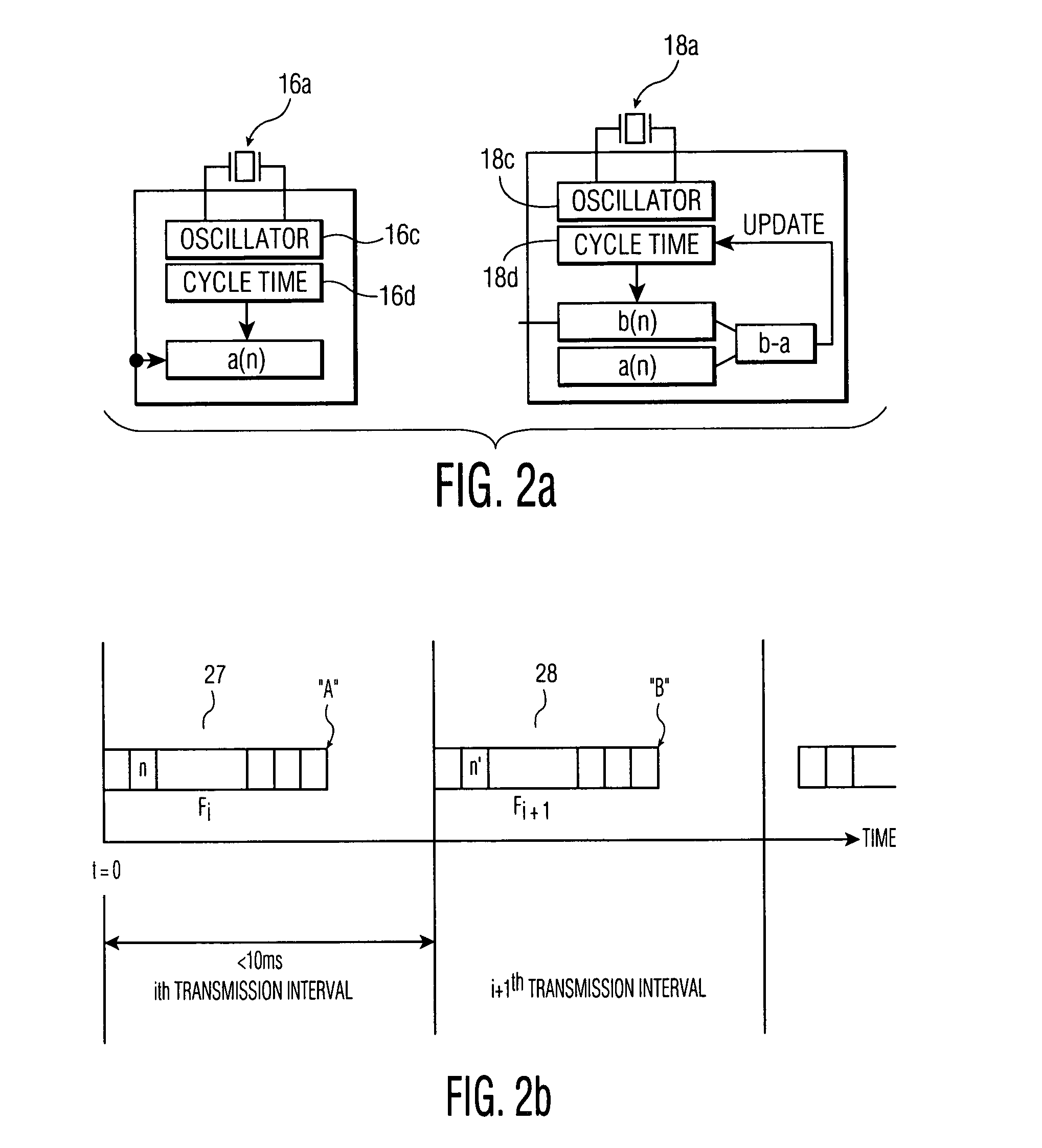
The present invention provides a system and method for synchronizing clocks in nodes connected via a wireless local area network (WLAN). The method involves transmitting synchronization frames from a master node to non-master nodes at regular intervals. The non-master nodes then save the current cycle time value and the sequence number of the synchronization frame upon receiving it. The master node then transmits the next synchronization frame including the saved cycle time and sequence number. The non-master nodes compute the difference between the saved cycle time and the current cycle time and adjust their local time base accordingly. This allows for accurate synchronization of clocks in nodes connected via WLAN.

Problems solved by technology

Due to the unavoidable drift of local clocks, a global time base can only be achieved by means of a clock synchronization protocol.
However, retrofitting wired IEEE 1394.1 bridges in existing residences may prove cost-prohibitive for many residences due to the extensive rewiring which will be required.

Method used


Image

  • System and method for performing clock synchronization of nodes connected via a wireless local area network
  • System and method for performing clock synchronization of nodes connected via a wireless local area network
  • System and method for performing clock synchronization of nodes connected via a wireless local area network

Examples


Embodiment Construction

[0022]In the following detailed description of the present invention, numerous specific details are set forth in order to provide a thorough understanding of the present invention. However, it will be apparent to one skilled in the art that the present invention may be practiced without these specific details. For the purposes of clarity and simplicity, well-known structures and devices are shown in block diagram form, rather than in detail, in order to avoid obscuring the present invention.

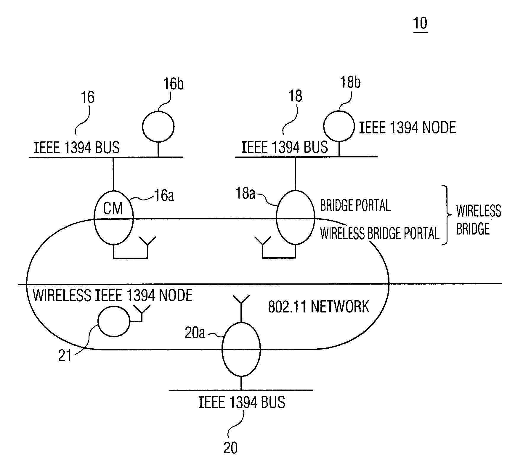
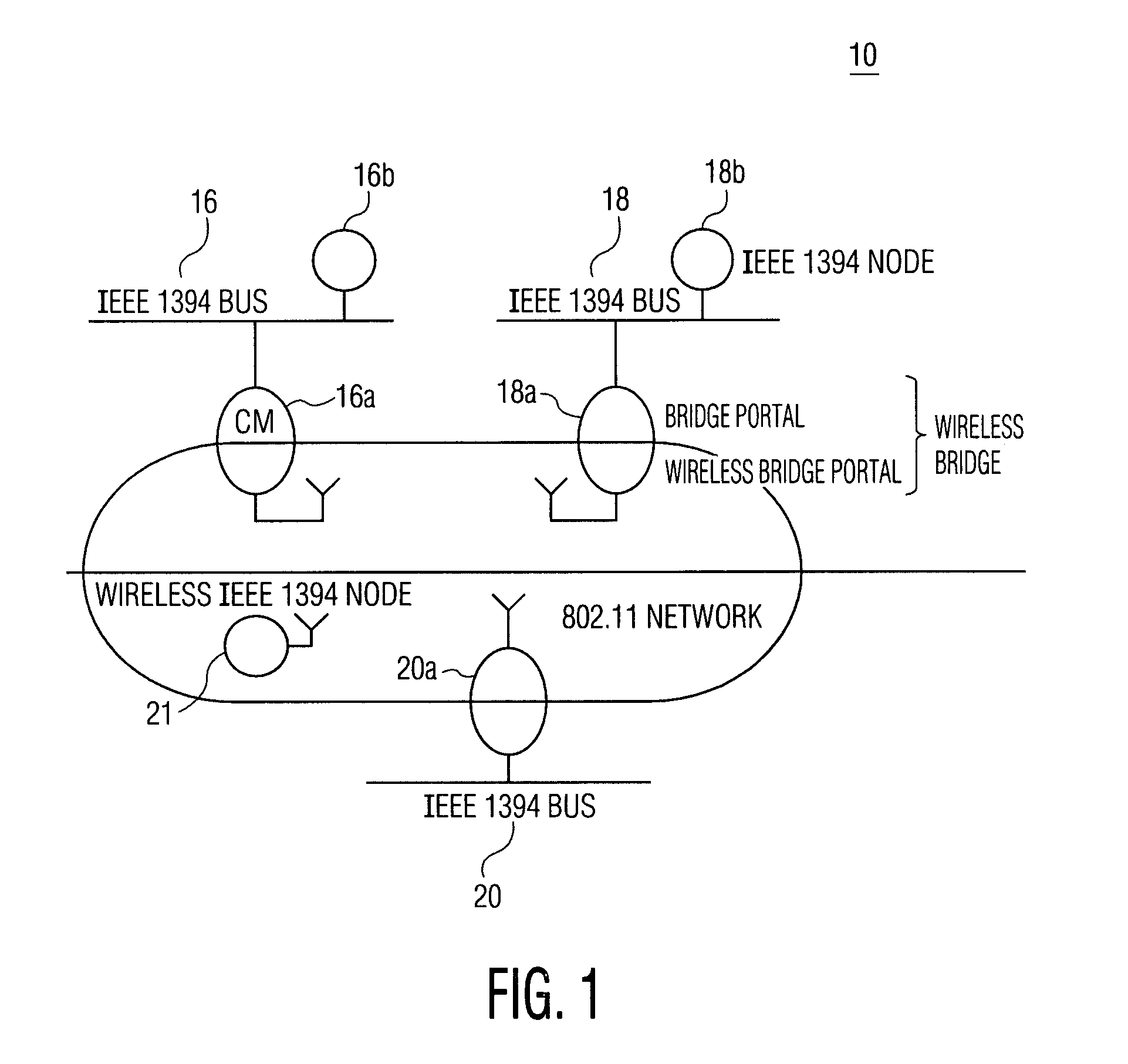
[0023]The present invention is described below in the context of synchronizing 1394 wireless nodes via an 802.11 wireless LAN. However, it is to be appreciated that the teachings of the invention discussed herein are not so limited. That is, the invention is applicable to any communication system, wired or wireless, that requires stringent synchronization as defined herein. For example, the present invention has applicability to wired communication systems, such as IEEE 802.3 and Ethernet.

[0024]W...


PUM


Abstract

A clock synchronization method and apparatus is disclosed for use in a communication system including a plurality of wireless nodes communicatively coupled via a wireless network, each of the plurality of wireless nodes having a local time base, and one of the plurality of wireless nodes being designated as a master node having a master time base which serves as a master clock against which the local time bases are synchronized. The clock synchronization method includes the steps of periodically transmitting synchronization frames to the plurality of non-master nodes so as to adjust the slave clocks associated with the respective non-master nodes. The synchronization frames are distributed from the master node at near-periodic intervals and includes a cycle time value that corresponds to the end of the previously transmitted synchronization frame. The slave clocks (i.e., non-master nodes) receiving the synchronization frame determine the cycle time value at the point of reception of the synchronization frame and adjusts their clocks by calculating a difference value between the received cycle time and a previously saved local cycle time value.

Description

CROSS REFERENCE TO RELATED APPLICATION[0001]This application claims the benefit of U.S. Provisional Application Ser. No. 60 / 362,518 filed on Mar. 7, 2002, the teachings of which are incorporated herein by reference.BACKGROUND OF THE INVENTION[0002]1. Field of the Invention[0003]The present invention relates generally to clock synchronization, and more particularly, to a clock synchronization protocol for performing stringent clock synchronization across multiple nodes.[0004]2. Description of the Related Art[0005]High precision clock synchronization is one of the most basic requirements in distributed real-time systems. Due to the unavoidable drift of local clocks, a global time base can only be achieved by means of a clock synchronization protocol.[0006]The present invention, in its broadest application, is directed to a clock synchronization protocol for wirelessly synchronizing clock registers of nodes via a wireless local area network (e.g., 802.11 network). The present invention...

Claims


Application Information

Patent Timeline
Patent Type & Authority Patents(United States)
IPC IPC(8): G04C11/00H04J3/06H04L7/00
CPCH04J3/0655
Inventor DEL PRADO PAVON, JAVIERNANDAGOPALAN, SAI SHANKARCHOI, SUNGHYUNSATO, TAKASHIBENNET, JEFF
Owner KONINKLIJKE PHILIPS ELECTRONICS NV
Learn More