Integrating SIP control messaging into existing communication center routing infrastructure

a communication center and messaging technology, applied in the field of telephony communication, can solve the problems of reducing the service life of the communication center, so as to achieve the effect of ensuring the service life and ensuring the quality of the communication, and ensuring the continuity of communication

Inactive Publication Date: 2006-10-10
GENESYS TELECOMMUNICATIONS LABORATORIES INC
View PDF9 Cites 22 Cited by
  • Summary
  • Abstract
  • Description
  • Claims
  • Application Information

AI Technical Summary

Problems solved by technology

Therefore, bandwidth is not guaranteed.
As a result, real-time voice communication may at times suffer dropout and delay.
This is at least partially due to packet loss experienced during periods of less-than-needed bandwidth which may prevail under certain conditions such as congestion during peak periods of use, and so on.
However, telephony, trunks and IPNT network lines representing the separate networks involved still provide for significant costs and maintenance.
Routing and other equipment, however, must be implemented at both the call-center level and network level significantly reducing any realized cost savings.
A significant disadvantage of such a bridge, having dedicated equipment on each end, is the dedicated nature of individual channels over the bridging link.
Efficient use of bandwidth cannot be assured during variable traffic conditions that may prevail at certain times. For example, dedicated channels assigned to IPNT traffic would not be utilized if there were not enough traffic to facilitate their use.
Therefore, additional requirements for equipment and inefficiency regarding use of bandwidth are still factors.
The addition of dedicated hardware both at the network level and within the call center adds to the expense of providing such integrated data.

Method used


Image

  • Integrating SIP control messaging into existing communication center routing infrastructure
  • Integrating SIP control messaging into existing communication center routing infrastructure
  • Integrating SIP control messaging into existing communication center routing infrastructure

Examples


Embodiment Construction

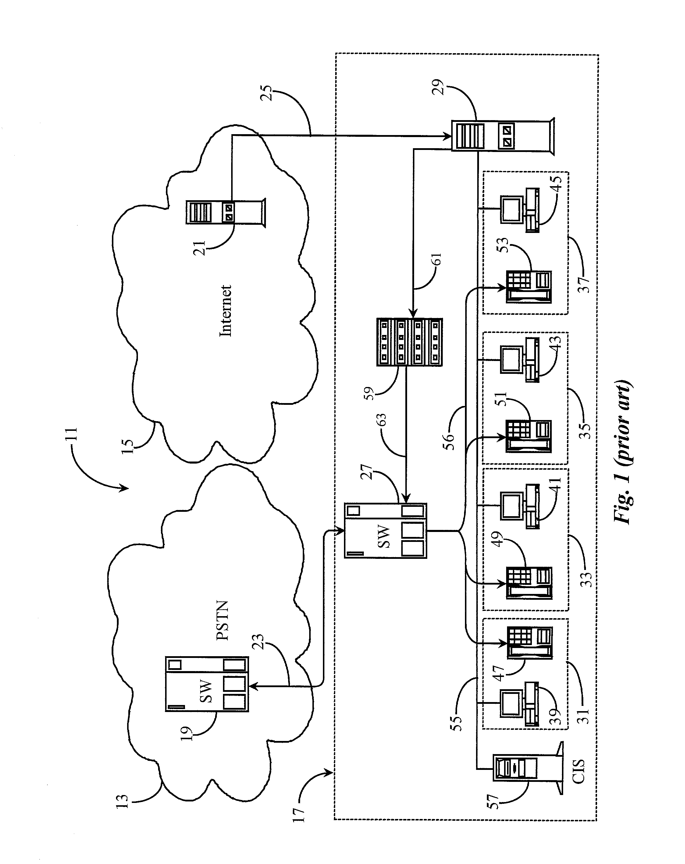
[0039]FIG. 1 is a system diagram of a call center connected to a telecommunication network using IPNT to COST conversion according to prior art. As described briefly with regards to the background section, various prior art telecommunication networks utilize network-bridging techniques for the purpose of causing IPNT and COST incoming calls to run parallel into the call center. In current systems, as was also described, various implementations have been made within the call center for converting IPNT to COST, and conversely, COST to IPNT. FIG. 1 represents one such current art system.

[0040]In FIG. 1 telecommunications network 11 comprises a publicly-switched telephone network (PSTN) 13, the Internet network 15, and a call center 17. PSTN network 13 may be a private network rather than a public network, and Internet 15 may be another public or a private data network as are known in the art.

[0041]In this basic prior art example, call center 17 is equipped to handle both COST calls and...


PUM


Abstract

A software suite is disclosed for routing communication events over a data-packet-network using an IP session initiation and management protocol. The software suite comprises, a server application running on the network for computing and serving routing determinations per request, a session management application running on the network for initiating and managing routed and established session events, a parsing application running on the network for parsing request data received under session initiation protocol and a conversion application running on the network for converting data received under session initiation protocol into a routing request. All received communication requests for routing are in the form of the session initiation protocol wherein they are parsed and converted into routing requests processed by the server application and routed to determined destinations and wherein events are established as session events conducted under the session initiation and management protocol.

Description

CROSS-REFERENCE TO RELATED DOCUMENTS[0001]The present invention is a Continuation-In-Part (CIP) to a U.S. patent application Ser. No. 09 / 160,558, entitled “Method and Apparatus for Providing Integrated Routing for PSTN and IPNT Calls in a Call Center”, filed on Sep. 24, 1998, disclosure of which is incorporated herein in its entirety by reference. The inventor of the instant application has also participated in the document disclosure program and claims priority to the contents of document disclosure number 496199 dated Jun. 19, 2001.FIELD OF THE INVENTION[0002]The present invention is in the field of telephony communication and pertains more particularly to methods and apparatus for using session initiation protocol (SIP) in the routing infrastructure of a communication center.BACKGROUND OF THE INVENTION[0003]In the field of telephony communication, there have been many improvements in technology over the years that have contributed to more efficient use of telephone communication ...

Claims


Application Information

Patent Timeline
Patent Type & Authority Patents(United States)
IPC IPC(8): H04L12/66H04L12/56H04L29/06H04M3/00H04M3/42H04M3/493H04M3/51H04M3/523H04M7/00H04Q3/58H04Q3/72
CPCH04L29/06027H04M3/5191H04M3/523H04L65/1006H04L65/4007H04M3/42323H04M3/493H04M7/006H04Q3/72H04L65/401H04L65/1104H04L65/1101
Inventor KIKINIS, DAN
Owner GENESYS TELECOMMUNICATIONS LABORATORIES INC
Why Eureka
Try Eureka