Wavelength reference apparatus and method

a wavelength reference and wavelength technology, applied in the direction of instruments, semiconductor lasers, optical elements, etc., can solve the problems of small channel separation, difficult to achieve goals, and the available wavelength reference systems used in external cavity lasers and other optical systems are subject to chang

Inactive Publication Date: 2006-10-10
INTEL CORP
View PDF151 Cites 23 Cited by
  • Summary
  • Abstract
  • Description
  • Claims
  • Application Information

AI Technical Summary

Problems solved by technology

Greater bandwidth requirements will likely result in smaller channel separation in the future.
These goals have been difficult to achieve.
Available wavelength reference systems used in external cavity lasers and other optical systems are subject to change due to aging and related changes in optical components during use, and can be unreliable.

Method used


Image

  • Wavelength reference apparatus and method
  • Wavelength reference apparatus and method
  • Wavelength reference apparatus and method

Examples


Embodiment Construction

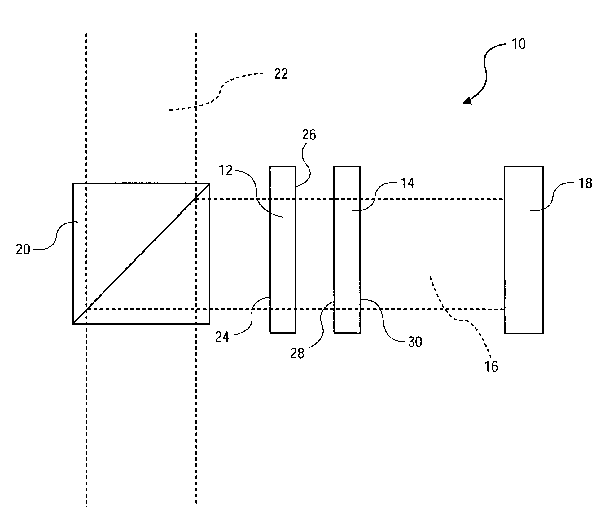
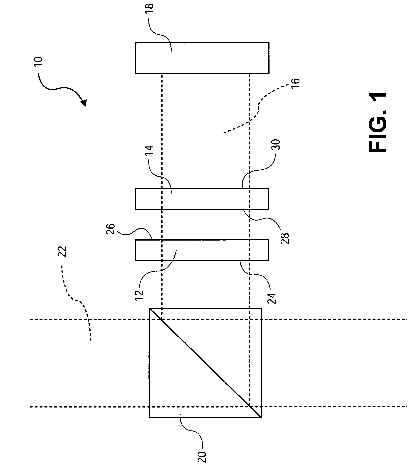
[0027]Referring more specifically to the drawings, for illustrative purposes the present invention is embodied in the apparatus shown in FIG. 1 through FIG. 10. It will be appreciated that the apparatus may vary as to configuration and as to details of the parts, and that the method may vary as to details and the order of the acts, without departing from the basic concepts as disclosed herein. The invention is disclosed primarily in terms of use with an external cavity laser. The invention, however, may be used with various types of laser devices and optical systems. The relative sizes of components and distances therebetween as shown in the drawings are in many instances exaggerated for reason of clarity, and should not be considered limiting. Any definitions herein are provided for reason of clarity, and should not be considered as limiting, and any technical and scientific terms used herein are intended to have the same meaning as commonly understood by those skilled in the art. ...


PUM


Abstract

Apparatus and methods usable for wavelength references and measurement of wavelength of a light beam. The apparatus comprise at least two wavelength reference or filter elements positioned in a light beam, each wavelength reference element having a different free spectral range and operable to define a joint free spectral range, and a detector positioned in the beam after the wavelength reference elements. The joint free spectral range provided by the multiple wavelength reference elements results in a joint transmission peak that is centered at a unique wavelength, and maximum optical power detectable from the beam by the detector occurs at the center wavelength of the joint transmission peak.

Description

[0001]This application is a continuation-in-part of U.S. patent application Ser. No. 09 / 626,526, filed Jul. 27, 2000 now U.S. Pat. No. 6,879,619 and a CIP U.S. patent application Ser. No. 10 / 099,649, filed Mar. 15, 2002 now U.S. Pat. No. 6,853,654; and is entitled to the benefits of U.S. Provisional Application No. 60 / 276,645, filed Mar. 16, 2001, U.S. Provisional Application No. 60 / 276,813, Mar. 16, 2001, U.S. Provisional Application Ser. No. 60 / 276,643, filed Mar. 16, 2001, U.S. Provisional Application No. 60 / 276,760, filed Mar. 16, 2001 and U.S. Provisional Application Ser. No. 60 / 276,646, filed Mar. 16, 2001, the disclosures of which are incorporated herein by reference.BACKGROUND OF THE INVENTION[0002]There is an increasing demand for tunable lasers for test and measurement uses, wavelength characterization of optical components, fiberoptic networks and other applications. In dense wavelength division multiplexing (DWDM) fiberoptic systems, multiple separate data streams propag...

Claims


Application Information

Patent Timeline
Patent Type & Authority Patents(United States)
IPC IPC(8): H01S3/13G02B5/28G02B6/34H01S5/14
CPCG02B5/281H01S5/141G02B6/29358G02B6/4215
Inventor MCDONALD, MARKRICE, MARKDAIBER, ANDREWCHAPMAN, WILLIAM B.
Owner INTEL CORP
Why Eureka
Try Eureka