
Method and apparatus to evaluate an intake air temperature monitoring circuit

a technology of temperature monitoring circuit and intake air, which is applied in the direction of electric control, machines/engines, instruments, etc., can solve the problems of engine fueling, engine performance, driveability, or emissions, and engine performance, and achieve the effect of avoiding engine or vehicle diagnostic failure, avoiding engine or vehicle failure, and avoiding engine failur

Inactive Publication Date: 2006-10-10
DELPHI TECH INC
View PDF6 Cites 9 Cited by
  • Summary
  • Abstract
  • Description
  • Claims
  • Application Information

AI Technical Summary

Benefits of technology

The present invention provides an improved engine control system that monitors the temperature of the air that enters the engine. This is done by using a control system that includes an electronic controller and sensors to measure the intake air temperature and the temperature of the coolant. The electronic controller analyzes these measurements and adjusts the engine's operation to maintain optimal performance. The invention also includes a method to determine if the temperature measurements are accurate. Overall, the invention helps to improve engine performance and efficiency by monitoring and controlling the air that enters the engine.

Problems solved by technology

An inaccurate reading of one or more of the operating conditions has the potential to adversely affect engine performance, driveability, or emissions, or cause a false failure of one or more engine or vehicle diagnostics.
Intake air temperature reading may affect execution of another algorithm, e.g. wherein the intake air temperature reading affects calculated mass of air flowing to the engine, thus affecting engine fueling.
An improperly operating engine caused by an inaccurate intake air temperature reading may lead to increased engine-out and tailpipe emissions.
However, these diagnostic algorithms do not account for all intake air temperature sensing circuit failure modes encountered during vehicle operation.

Method used


Image

  • Method and apparatus to evaluate an intake air temperature monitoring circuit
  • Method and apparatus to evaluate an intake air temperature monitoring circuit
  • Method and apparatus to evaluate an intake air temperature monitoring circuit

Examples


Embodiment Construction

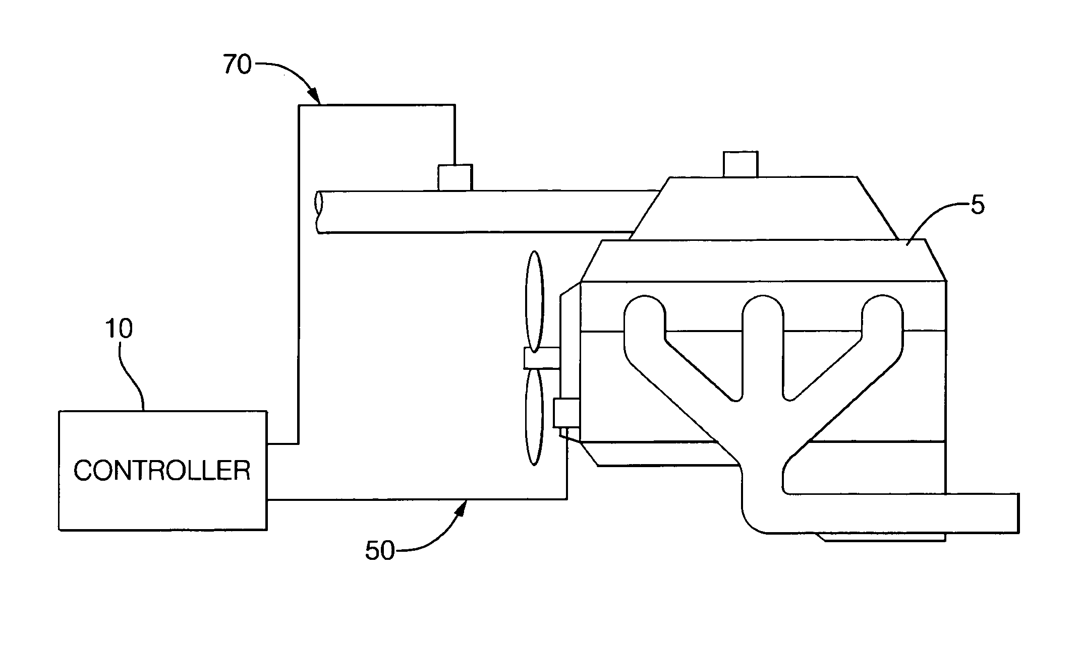
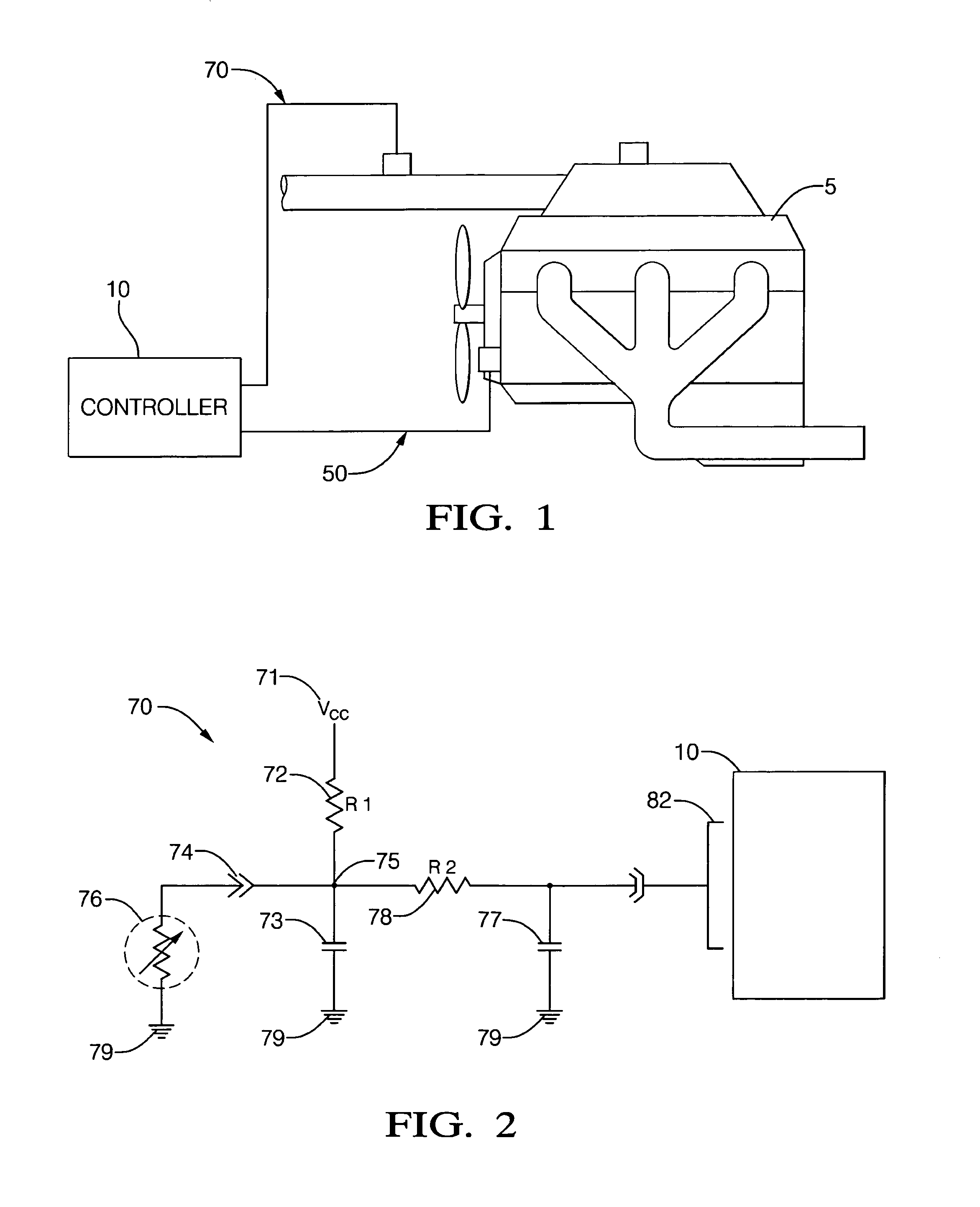
[0020]Referring now to the drawings, wherein the showings are for the purpose of illustrating the invention only and not for the purpose of limiting the same, FIG. 1 shows an internal combustion engine 5 and control system which has been constructed in accordance with an embodiment of the present invention. In the embodiment, the internal combustion engine and control system includes an electronic controller 10 operable to monitor an intake air temperature (also referred to hereinafter as ‘IAT’) sensing circuit 70 (See FIG. 2) for the internal combustion engine. The electronic controller 10 is signally connected to the intake air temperature sensing circuit 70, a coolant temperature sensing circuit including a coolant temperature sensor 50, and a plurality of other engine sensors (not shown). This allows the electronic controller 10 to measure intake air temperature, TAIR, coolant temperature, TCLT, and engine operating conditions. Using on-board algorithms and calibrations, the con...


PUM


Abstract

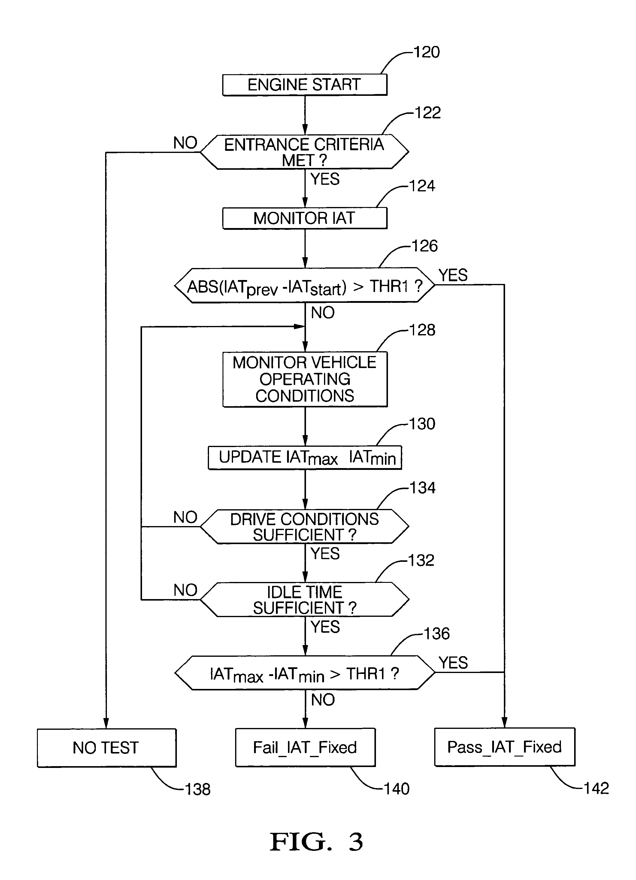
A control system and method to monitor an intake air temperature sensing circuit for an internal combustion engine is shown. The electronic controller is connected to the intake air temperature sensing circuit, coolant temperature sensor, and a plurality of other engine sensors. The controller determines whether the measured intake air temperature changes in response to a change in actual intake air temperature, based upon the engine operating conditions and the measured intake air temperature. The controller determines whether the measured intake air temperature is representative of actual intake air temperature, based upon the measured intake air temperature, the coolant temperature, and at least one engine operating condition. The invention is an element of an on-board diagnostic system, typically related to vehicle emissions.

Description

TECHNICAL FIELD[0001]This invention pertains generally to internal combustion engine control systems, and more specifically to a method and apparatus related to the engine control system wherein performance of an intake air temperature sensing circuit is monitored and abnormalities are detected.BACKGROUND OF THE INVENTION[0002]A typical engine control system for a modern spark ignition internal combustion engine includes an electronic controller operable to measure engine operating conditions and operator inputs, and operable to control various systems and actuators based upon the measured conditions and inputs. The typical electronic controller includes an interface electrically connected to a plurality of engine and vehicle sensors via one or more wiring harnesses. The engine and vehicle sensors measure various engine operating conditions and operator demands. Measured conditions include intake air temperature, as well as other engine conditions, including for example, engine rota...

Claims


Application Information

Patent Timeline
Patent Type & Authority Patents(United States)
IPC IPC(8): G06F19/00
CPCF01P11/14F02D41/222F01P2025/08F01P2025/13F01P2025/42F01P2025/60F01P2031/00F02D2200/0414
Inventor RAHMAN, MAHFUZURSIMPSON, KENNETH M.TRANQUILLI, PAULO F. R.
Owner DELPHI TECH INC
Learn More