Manufacturing method and manufacturing apparatus for wheel-support rolling bearing unit

a technology of rolling bearing unit and manufacturing method, which is applied in the direction of bearing unit rigid support, forging/pressing/hammering apparatus, forging presses, etc., can solve the problems of unable to form the crimped portion, loss of durability of the components of this manufacturing apparatus, etc., and achieve the effect of suppressing the increase in the torque required to rotate the outer diameter raceway member and preventing the formation of indentations on each raceway

Inactive Publication Date: 2006-10-17
NSK LTD
View PDF11 Cites 18 Cited by
  • Summary
  • Abstract
  • Description
  • Claims
  • Application Information

AI Technical Summary

Benefits of technology

[0018]The wheel-support rolling bearing unit which is the subject of the manufacturing method and manufacturing apparatus for a wheel-support rolling bearing unit of the present invention, is provided with an outer diameter raceway member having first and second outer raceways on an inner peripheral surface, an inner diameter raceway member having first and second inner raceways on an outer peripheral surface, and a plurality of rolling elements provided so as to rotate freely between the first and second inner raceways and the first and second outer raceways.
[0024]According to the manufacturing method and manufacturing apparatus for a wheel-support rolling bearing unit of the present invention configured as described above, since the crimped portion is formed while rotating the outer diameter raceway member, the formation of indentations on each raceway is prevented. Moreover, since a difference is provided between the rotational velocity of the compression member and the rotational velocity of the rolling elements (preferably the difference is at least 10 min−1), an increase in the torque required to rotate the outer diameter raceway member can be suppressed.

Problems solved by technology

When the torque increases further, the durability of the components of this manufacturing apparatus is lost.
When the torque increases even further, it becomes no longer possible to form the crimped portion.

Method used


Image

  • Manufacturing method and manufacturing apparatus for wheel-support rolling bearing unit
  • Manufacturing method and manufacturing apparatus for wheel-support rolling bearing unit
  • Manufacturing method and manufacturing apparatus for wheel-support rolling bearing unit

Examples


Embodiment Construction

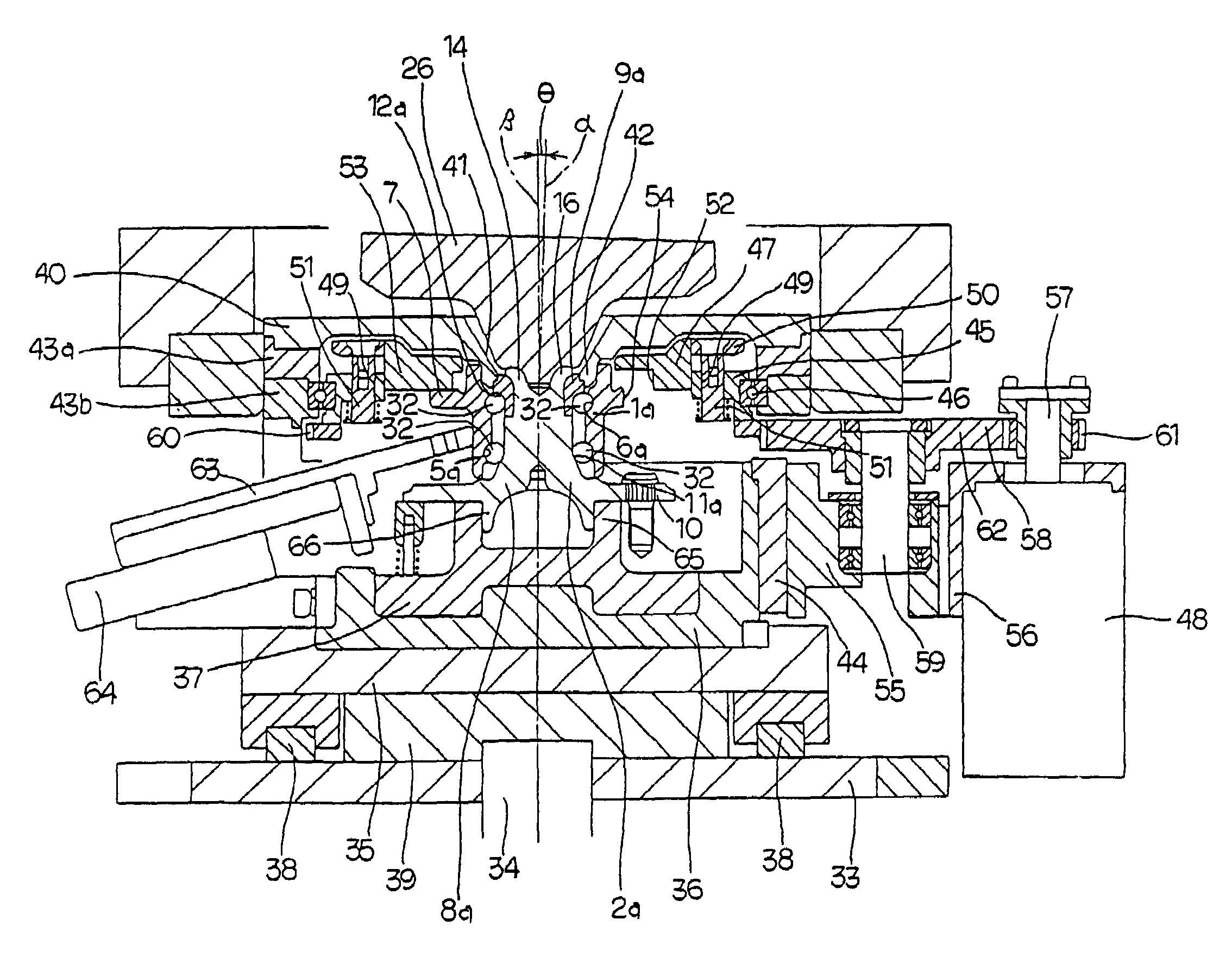
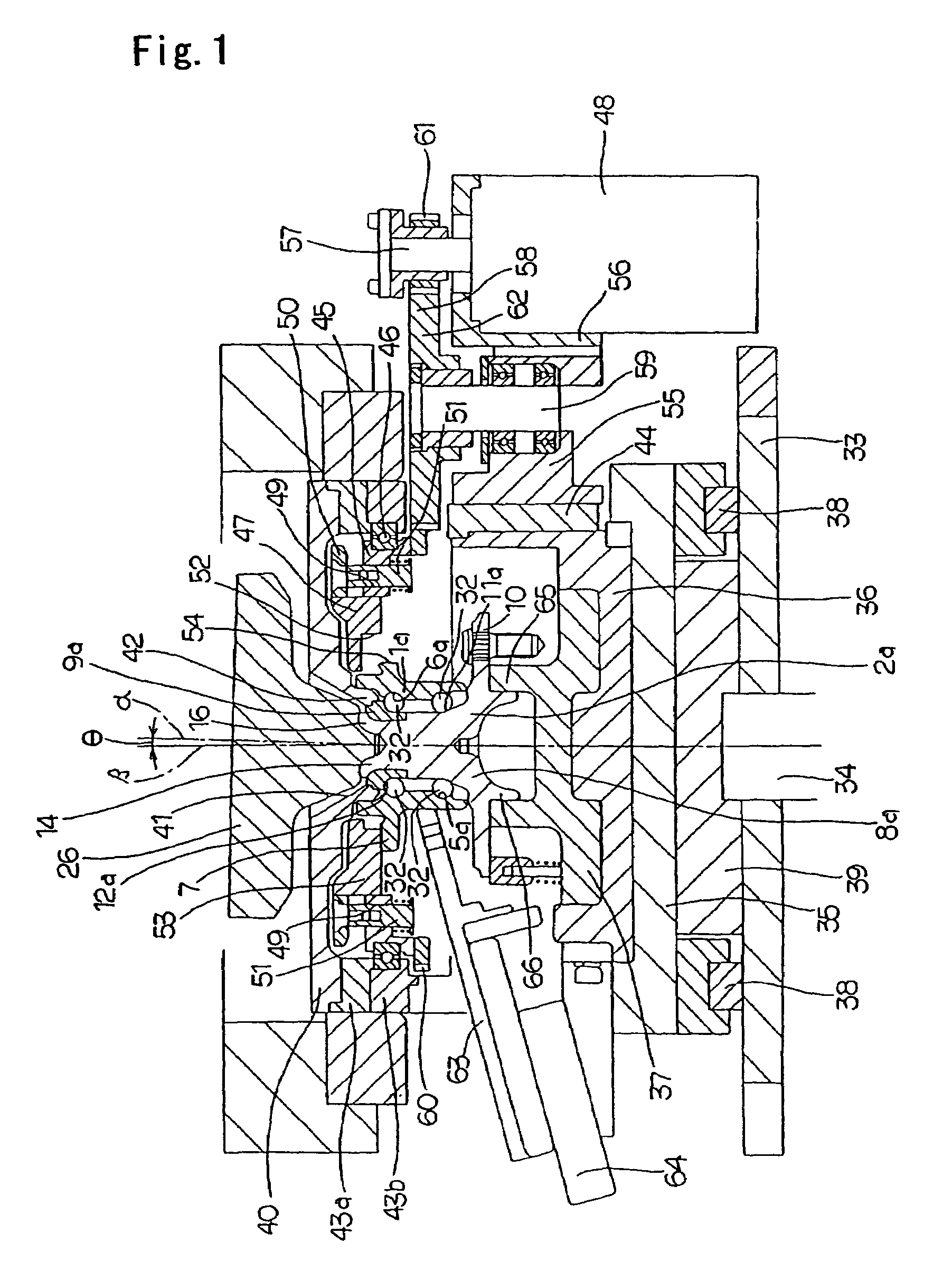
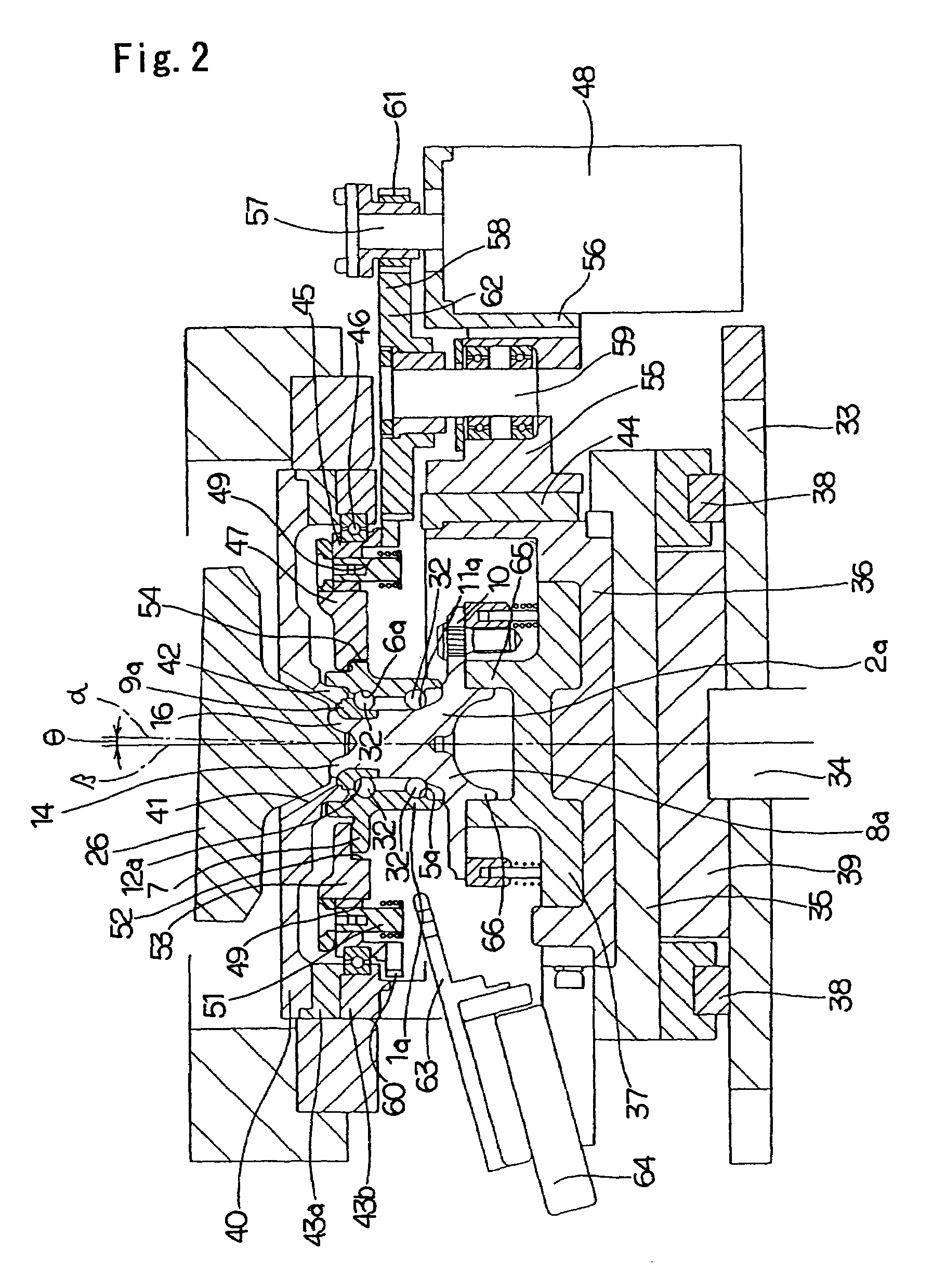
[0036]FIG. 1 and FIG. 2 show one example of an embodiment of the present invention. As explained above, when balls are employed as the rolling elements, indentations are readily formed in the surface of the raceway in association with formation of the crimped portion. That is to say, this effect is particularly apparent when the present invention is applied to a wheel-support rolling bearing unit employing balls as rolling elements. Therefore in the example shown in the figure, balls 32 are employed as the rolling elements. To match this, the cross-sectional shape of first and second inner raceways 11a and 12a formed on the outer peripheral surface of a hub 2a comprising first and second outer raceways 5a and 6a of the inner peripheral surface of an outer ring 1a, and a hub main body 8a and an inner ring 9a, are arc-shaped. Since the basic configuration of the wheel-support rolling bearing unit is the same as the aforementioned conventional structure shown in FIG. 8 apart from this ...


PUM

PropertyMeasurementUnit
angleaaaaaaaaaa
outer diameteraaaaaaaaaa
inner diameteraaaaaaaaaa

Abstract

In a manufacturing method and a manufacturing apparatus for a wheel-support rolling bearing unit, when forming a crimped portion 14 on an end (inside end) of a hub main body 8a, by rocking die forging using a die 26, while preventing enlargement of equipment, in order to prevent forming indentations in a second outer raceway 6a and a second inner raceway 12a, in the present invention, the outer ring 1a is turned by a motor 48, and the balls 32 are rotated. A difference is provided between the rotation speed of the balls 32 and an oscillation speed of the die 26. This difference is preferably at least 10 min−1. By rotating the balls 32 the formation of indentations in the second outer raceway 6a and the second inner raceway 12a is prevented. Moreover, by providing the difference between the rotation speed and the oscillation speed of the die 26, an increase in the torque required for rotation the outer ring 1a is suppressed.

Description

CROSS-REFERENCE TO RELATED APPLICATION[0001]This application is a continuation of an International Application No. PCT / JP03 / 07812, which was filed on Jun. 19, 2003 and claims priority from Japanese Patent Application 2002-182365 filed on Jun. 24, 2002, which is herein incorporated by reference.TECHNICAL FIELD[0002]The present invention relates to improvements in a manufacturing method for a wheel-support rolling bearing unit for rotatably supporting a vehicle wheel of an automobile in relation to a suspension device, and to a manufacturing apparatus employed in the implementation of this manufacturing method.BACKGROUND ART[0003]A wheel-support rolling bearing unit is employed for rotatable support of a vehicle wheel of an automobile in relation to a suspension device. A structure as shown in FIG. 8 is disclosed in the wheel-support rolling bearing unit of Japanese Unexamined Patent Publication No. 2000-343905. This wheel-support rolling bearing unit rotabably supports a hub 2 being ...

Claims


Application Information

Patent Timeline
Patent Type & Authority Patents(United States)
IPC IPC(8): B21D53/10B23P19/04B21J9/02B21K23/04B21K25/00B23P11/00B60B27/00F16C19/00F16C19/38F16C33/64F16C35/063F16C43/04
CPCB21J9/025B21K25/00B23P11/00B60B27/00F16C33/64F16C43/04F16C19/186B21K23/04Y10T29/49682Y10T29/49915Y10T29/497Y10T29/53109Y10T29/49536Y10T29/4968Y10T29/49696Y10T29/49535Y10T29/53104Y10T29/49643F16C19/386F16C2326/02
Inventor YASUMURA, MASAHIROHAGIWARA, NOBUYUKIHORIKE, SHOJI
Owner NSK LTD
Why Eureka
Try Eureka