Combustor dome assembly of a gas turbine engine having improved deflector plates

a technology of deflector plates and combustion domes, which is applied in the direction of combustion process, hot gas positive displacement engine plants, lighting and heating apparatus, etc., to achieve the effect of reducing stress

Active Publication Date: 2006-10-17
GENERAL ELECTRIC CO
View PDF13 Cites 44 Cited by
  • Summary
  • Abstract
  • Description
  • Claims
  • Application Information

AI Technical Summary

Benefits of technology

[0007]In a second exemplary embodiment of the invention, a deflector plate for a gas turbine engine combustor is disclosed as having a longitudinal centerline axis therethrough. The deflector plate includes: an annular section at an upstream end thereof having a forward end, an aft end, an inner surface and an outer surface; a substantially planar flange connected to the aft end of the annular section, the planar flange including an outer circumferential surface, an inner circumferential surface, a first radial surface, a second radial surface, and an opening therein sized to the inner surface of the annular section so as to form opposing radial sections; a first flange connected to the outer circumferential surface of the planar flange at a predetermined angle thereto; and, a second flange connected to the inner circumferential surface of the planar flange at a predetermined angle thereto. The first and second radial sections include a notched portion therein so as to reduce stress imposed on the radial sections of the planar flange.

Problems solved by technology

It has been found, however, that the proximity of adjacent deflector plates and the relatively thin radial sections thereof has created additional stresses which have created deformation and cracking along portions thereof.

Method used


Image

  • Combustor dome assembly of a gas turbine engine having improved deflector plates
  • Combustor dome assembly of a gas turbine engine having improved deflector plates
  • Combustor dome assembly of a gas turbine engine having improved deflector plates

Examples


Embodiment Construction

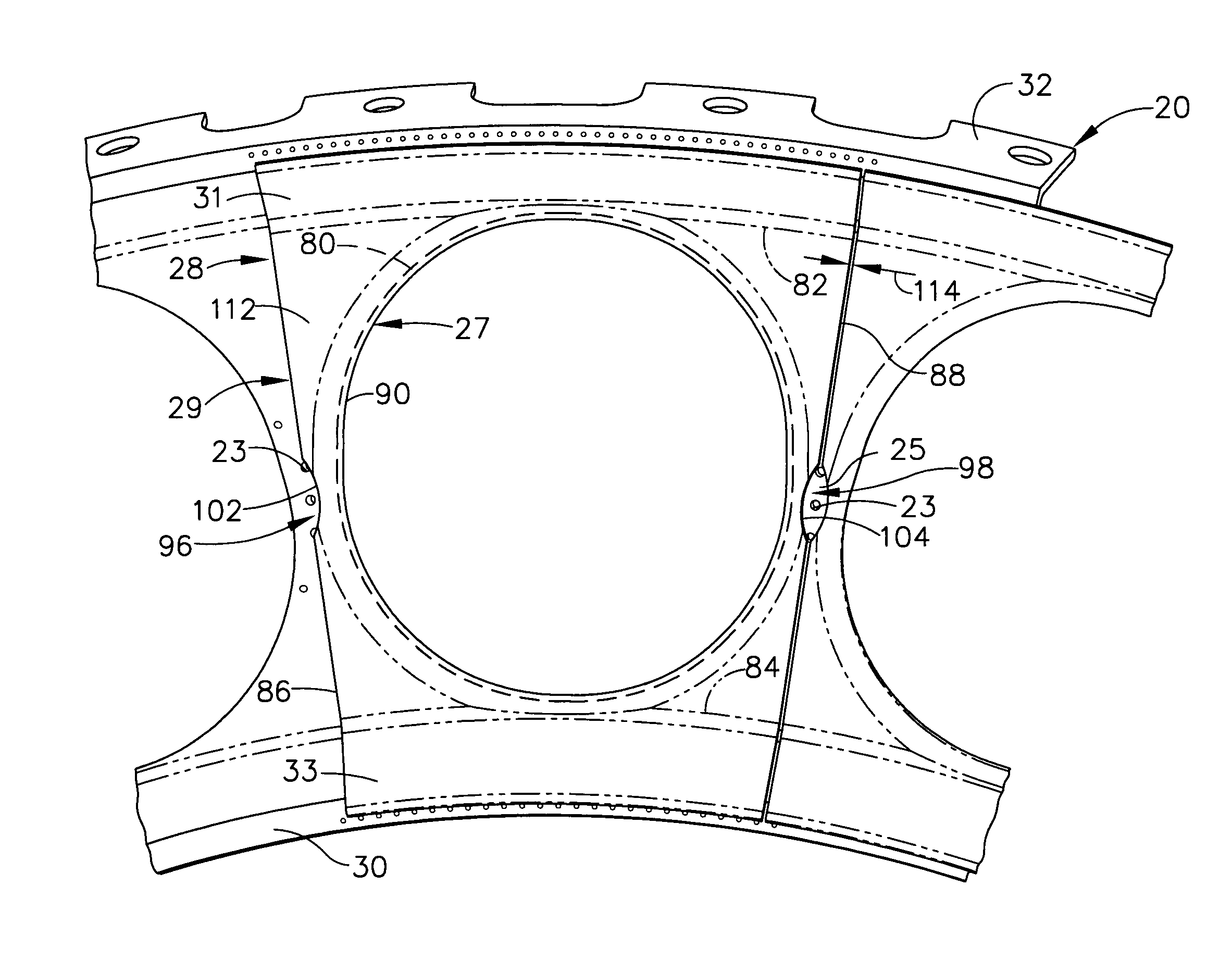
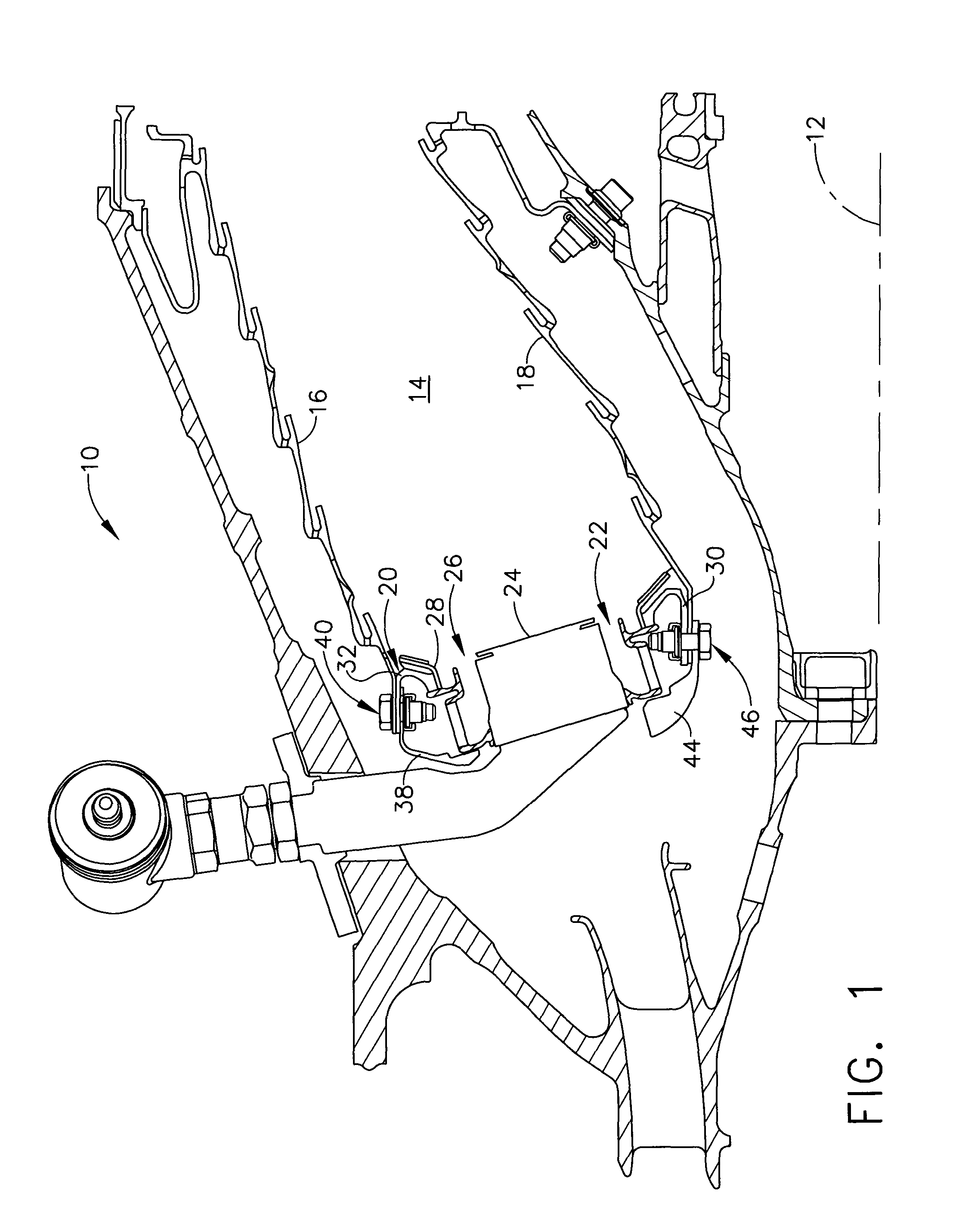
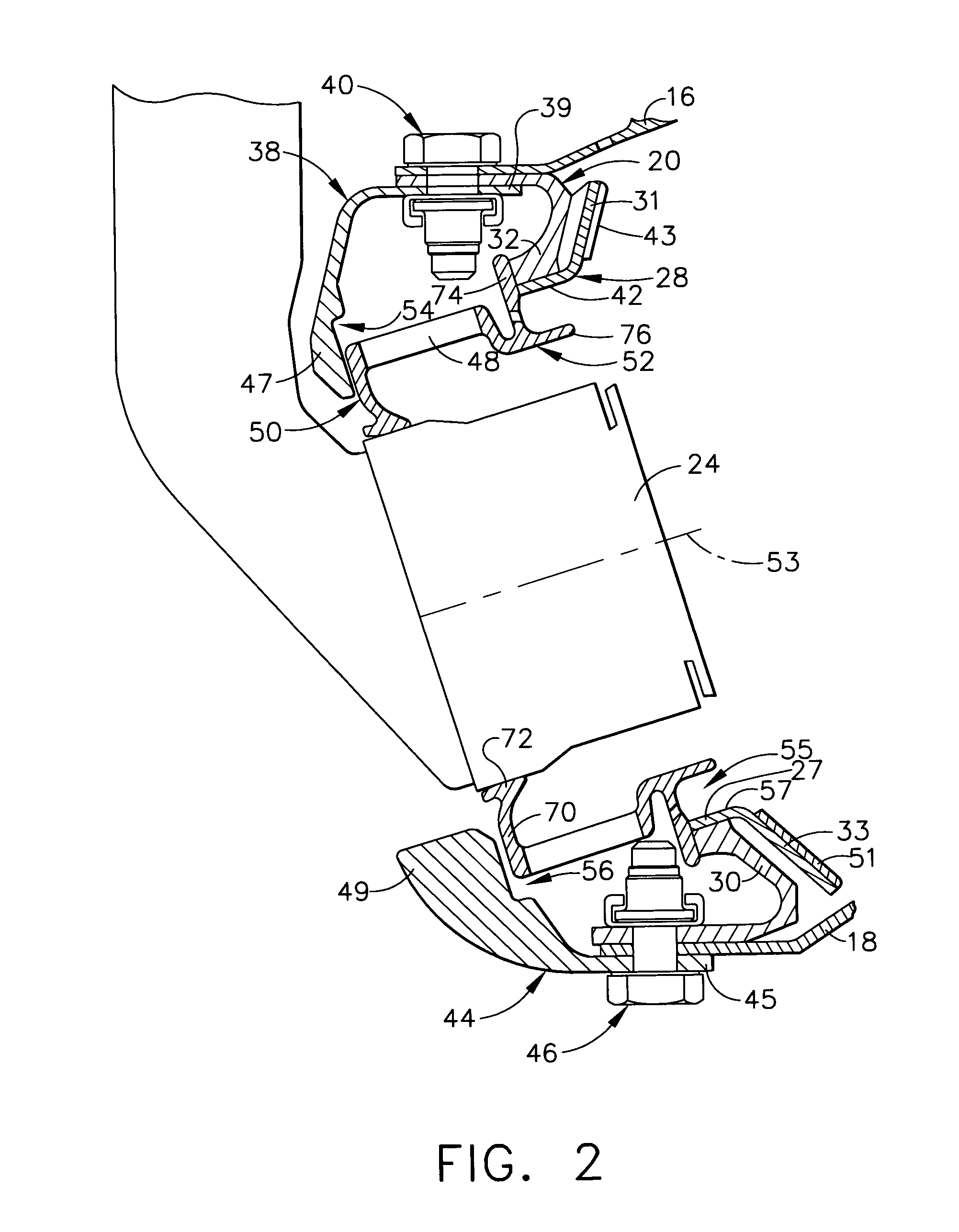
[0018]Referring now to the drawings in detail, wherein identical numerals indicate the same elements throughout the figures, FIG. 1 depicts an exemplary gas turbine engine combustor 10 having a longitudinal centerline axis 12 extending therethrough. Combustor 10 includes a combustion chamber 14 defined by an outer liner 16, an inner liner 18, and a dome plate 20 located at an upstream end thereof. It will be understood that a plurality of fuel / air mixers 22 are circumferentially spaced within dome plate 20 so as to introduce a mixture of fuel and air into combustion chamber 14, where it is ignited by an igniter (not shown) and combustion gases are formed which are utilized to drive one or more turbines downstream thereof. More specifically, each air / fuel mixer 22 preferably includes a fuel nozzle 24, a swirler 26, and a deflector plate 28.

[0019]More specifically, it will be understood that dome plate 20 is annular in configuration and includes an inner portion 30, an outer portion 3...


PUM


Abstract

A combustor dome assembly for a gas turbine engine having a longitudinal centerline axis extending therethrough, including: an annular dome plate having an inner portion, an outer portion, a forward surface, and a plurality of circumferentially spaced openings formed therein, wherein a radial section defined between each of the openings includes a cooling trough formed therein; an outer cowl connected to the dome plate outer portion at a downstream end thereof; an inner cowl connected to the dome plate inner portion at a downstream end thereof; and, a deflector plate connected to and positioned aft of each opening in the dome plate. Each deflector plate further includes: an annular section at an upstream end thereof having a forward end, an aft end, an inner surface and an outer surface; a substantially planar flange connected to the aft end of the annular section, the planar flange including an outer circumferential surface, an inner circumferential surface, a first radial surface, a second radial surface, and an opening therein sized to the inner surface of the annular section so as to form opposing radial sections; a first flange connected to the outer circumferential surface of the planar flange at a predetermined angle thereto; and, a second flange connected to the inner circumferential surface of the planar flange at a predetermined angle thereto. The first and second radial sections of the deflector plate planar flange are configured so at least a portion of the dome plate cooling trough is in flow communication with a combustion chamber downstream of said dome plate.

Description

BACKGROUND OF THE INVENTION[0001]The present invention relates generally to a combustor dome assembly for a gas turbine engine and, in particular, to a combustor dome assembly including deflector plates which are configured to limit stress imposed thereon. Further, a dome plate for the combustor dome assembly is provided which has a cooling trough in each radial section with purge openings that are substantially aligned with a radial surface of such deflector plates.[0002]It is well known within the combustor art of gas turbine engines that a dome portion, in conjunction with inner and outer liners, serves to form the boundary of a combustion chamber. A mixture of fuel and air is ignited and burned in such combustion chamber so that the products thereof are able to interface with the blades of turbines and produce work through one or more shafts. The annular combustor dome also serves to position a plurality of mixers in a circumferential manner so that a fuel / air mixture is provide...

Claims


Application Information

Patent Timeline
Patent Type & Authority Patents(United States)
IPC IPC(8): F02C1/00F23R3/10F23R3/14F23R3/42F23R3/60
CPCF23R3/10F23R2900/00005
Inventor MCMASTERS, MARIE ANNVANDIKE, JOHN LAWRENCECOOPER, JAMES NEILVERMEERSCH, MICHAEL LOUISTHOMSEN, DUANE DOUGLASDANIS, ALLEN MICHAEL
Owner GENERAL ELECTRIC CO
Why Eureka
Try Eureka