
Stabiliser bar for a motor vehicle

Inactive Publication Date: 2006-10-17
ZF LEMFOERDER METALLWAREN AG
View PDF26 Cites 19 Cited by
  • Summary
  • Abstract
  • Description
  • Claims
  • Application Information

AI Technical Summary

Benefits of technology

[0010]The object of the present invention is to provide an inexpensive roll bar which is always sufficiently effective during travel in a curve as well as in evading maneuvers and also affects the spring action characteristics of the vehicle only slightly in order to guarantee a high level of driving smoothness.
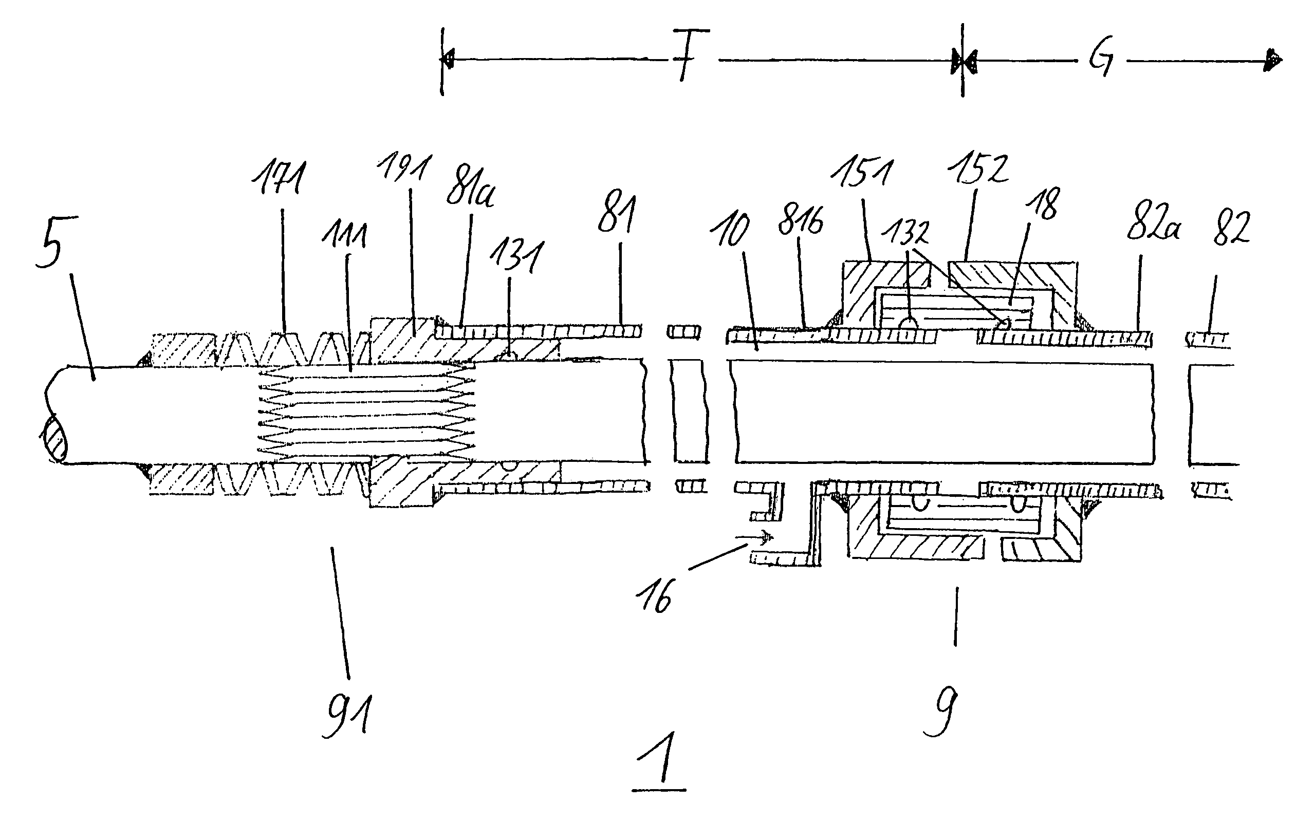
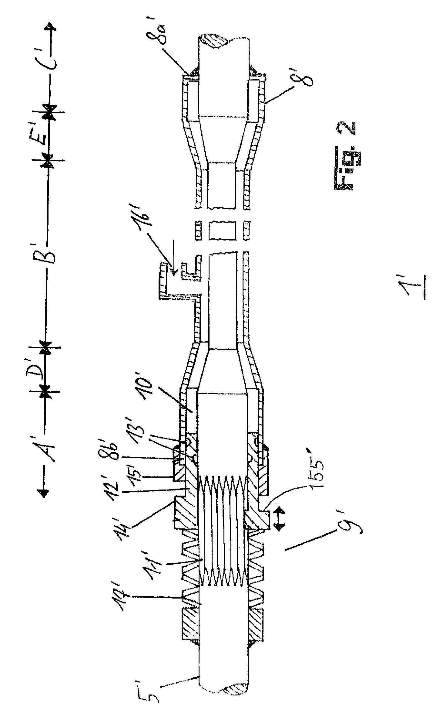
[0011]According to the present invention, a roll bar for a motor vehicle is provided, which has an unsplit torsion bar, which is fastened rotatably to a vehicle chassis, is connected to two opposite wheel suspensions of the same axle of the vehicle and has a torsion area for the elastic coupling of spring action movements of the opposite wheel suspensions, wherein the roll bar has, furthermore, a first torsion tube, which surrounds the unsplit torsion bar in at least one first partial area of its torsion area and whose first end is connected to the unsplit torsion bar, rotating in unison, and whose second end can be connected to the unsplit torsion bar by means of a clutch arrangement, selectively rotating in unison, so that the torsional stiffness of the roll bar can be varied.
[0012]Thus, the spring action movements of the opposite wheel suspensions are not fully uncoupled according to the present invention, but only the torsional stiffness of the clutch arrangement is changed. Therefore, it is also not necessary to design the clutch arrangement to the maximum torsional stiffness of the roll bar, but only to the torsional stiffness of the torsion tube, as a result of which the clutch arrangement can have a simpler design and can consequently be manufactured at a lower cost. A minimum of elastic coupling of the spring action movements of the opposite wheel suspensions is always guaranteed in the roll bar according to the present invention even in case of complete failure of the clutch arrangement.

Problems solved by technology

However, if the pavement is so uneven that one wheel on one side of the vehicle is forced in the inward deflection direction, while the corresponding wheel on the other side of the vehicle must be moved in the outward deflection direction to maintain the desired road contact, the driving smoothness is compromised by a roll bar, because the roll bar tends to counteract mutually opposite movements of the wheel suspensions coupled by the roll bar relative to the vehicle body.
Thus, during straight-line travel, a roll bar may undesirably cause vibrations of one wheel to be transmitted to the opposite wheel of the same axle, which compromises the driving smoothness.
The drawback of the prior-art roll bars with torsion bar is that the switching on (coupling) of the roll bar during travel in a curve must take place, in general, automatically and very rapidly for safety reasons, because the vehicle could otherwise become uncontrollable in the curve.
The high costs of the prior-art roll bars which are associated with these requirements on the actuator have caused that switch-on roll bars (also known under the name “active roll bars”) are not used in models manufactured in large series (i.e., in vehicles manufactured in large numbers).
Furthermore, slow, manually switchable roll bars are known, which are used especially in off-the-road vehicles.
Such systems are not suitable for safety reasons for switching on and off the roll bar during travel on a normal road, because there is a risk that the roll bar will not be switched on or will not be switched on in time in a curve, and the vehicle will thus assume an uncontrollable state.

Method used


Image

  • Stabiliser bar for a motor vehicle
  • Stabiliser bar for a motor vehicle
  • Stabiliser bar for a motor vehicle

Examples


Embodiment Construction

[0043]Referring to the drawings in particular, identical elements are designated by identical reference numbers.

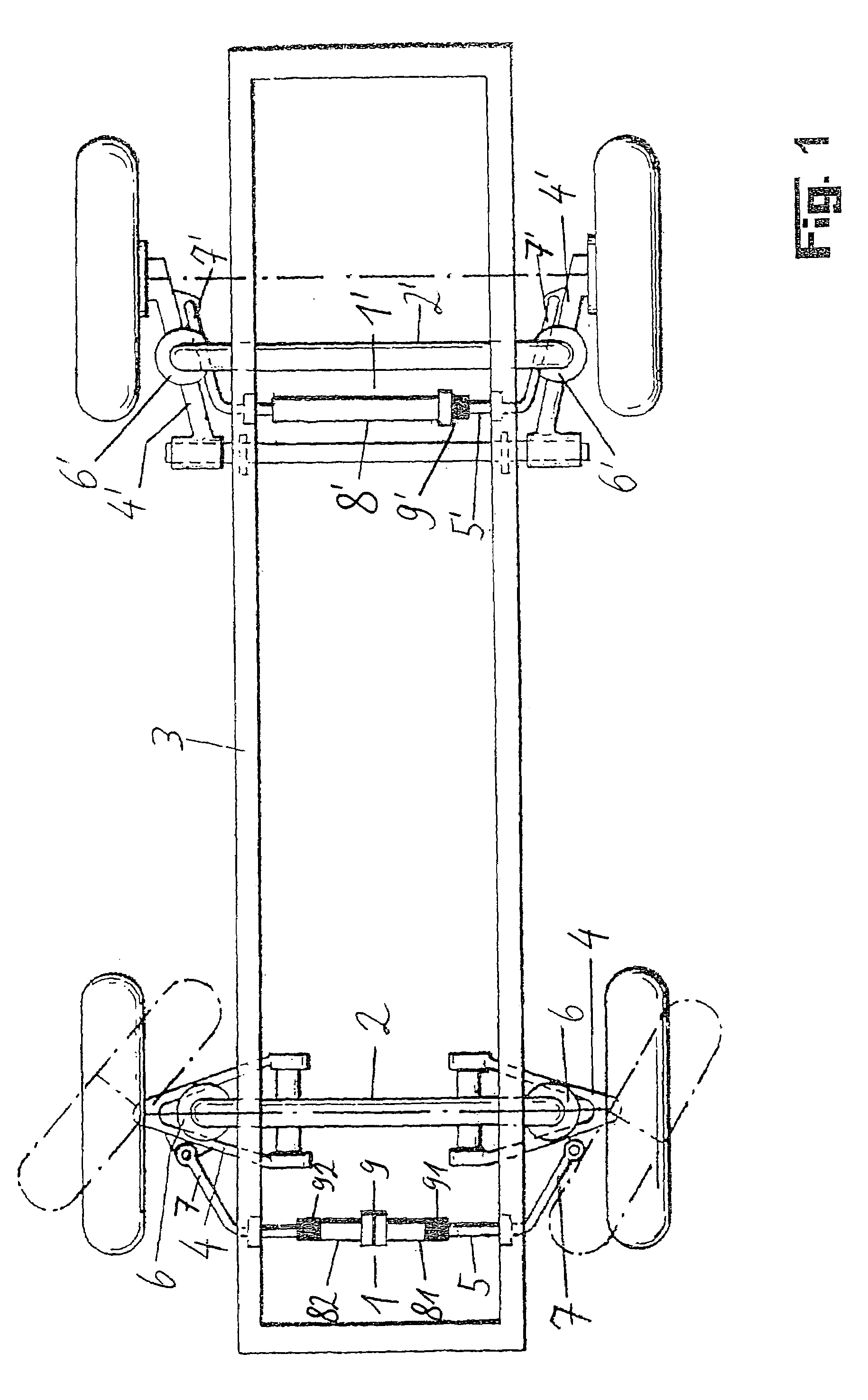
[0044]FIG. 1 shows how the roll bars 1, 1′ according to the present invention can be arranged in a motor vehicle. In the exemplary embodiment being shown, two different embodiments of the roll bar 1, 1′ according to the present invention are arranged on the front axle 2 and the rear axle 2′ of the vehicle. However, it is, of course, also possible as an alternative without any problems and may even be meaningful to arrange the same embodiment of the roll bar according to the present invention on both the front axle and the rear axle, or to arrange the roll bar according to the present invention on only one axle and to arrange a conventional roll bar on the other axle.

[0045]The roll bar 1, 1′ according to the present invention has an unsplit torsion bar 5, 5′ each, which is rotatably fastened to a vehicle chassis and is connected to two opposite wheel suspensions 4, 4′ of th...


PUM


Abstract

A roll bar (1′) for a motor vehicle is proposed according to the present invention, with an unsplit torsion bar (5′), which is rotatably fastened to a vehicle chassis (3), is connected to two opposite wheel suspensions (4′) of the said axle of the vehicle, and has a torsion area for the elastic coupling of spring action movements of the opposite wheel suspensions (4′), wherein the roll bar (1′) has, furthermore, a first torsion tube (8′), which surrounds the unsplit torsion bar (5′) at least in a first partial area (B′) of its torsion area, and whose first end (8a′) is connected to the unsplit torsion bar (5′), rotating in unison therewith, and whose second end (8b′) can be connected to the unsplit torsion bar (5′) by means of a clutch arrangement (9′) in such a way that it selectively rotates in unison therewith, so that the torsional stiffness of the roll bar (1′) can be varied.

Description

FIELD OF THE INVENTION[0001]The present invention pertains to a motor vehicle roll bar having a unsplit torsion bar, which is rotatably fastened to a vehicle chassis, is connected to two opposite wheel suspensions of the same axle of the vehicle and has a torsion area for elastically coupling spring action movements of the opposite wheel suspensions.BACKGROUND OF THE INVENTION[0002]Roll bars for motor vehicles are usually used to elastically couple the wheel suspension of a wheel on one side of the motor vehicle with the wheel suspension of the corresponding wheel of the same axle on the other side of the motor vehicle. The coupling is performed such that when one wheel is deflected inwardly, the spring action of the other wheel is also acted on in the direction of inward deflection. As a result, the lateral slope of the motor vehicle toward the outside of the curve is reduced during the travel of the motor vehicle in a curve, partly because the wheel suspension of the particular wh...

Claims


Application Information

Patent Timeline
IPC IPC(8): B60G21/055B60G17/016B60G17/027
CPCB60G17/0162B60G17/0277B60G21/0553B60G21/0556B60G2202/1351B60G2400/104B60G2400/204B60G2400/41B60G2400/44B60G2500/20B60G2800/24B60G17/015
Inventor ERSOY, METINVORTMEYER, JENS
Owner ZF LEMFOERDER METALLWAREN AG
Learn More