Droplet-jetting device with pressure chamber expandable by elongation of pressure-generating section

a technology of pressure-generating section and droplet-jetting device, which is applied in printing and other directions, can solve the problems of unsatisfactory energy efficiency, increased cost, and inability to supply ink-jet printers in time, and achieves the effects of enhancing resolution, expanding the volume of the pressure chamber, and forming with eas

Inactive Publication Date: 2006-10-17
BROTHER KOGYO KK
View PDF15 Cites 11 Cited by
  • Summary
  • Abstract
  • Description
  • Claims
  • Application Information

AI Technical Summary

Benefits of technology

[0026]The droplet-jetting device of the present invention may further comprise an actuator unit which covers the entire pressure chamber and which includes the pressure-generating section, wherein the pressure-generating section may be positioned opposingly to the first portion of the vibration plate, the vibration plate may abut against the pressure-generating section at the first portion, and a space may be formed between the second portion and the actuator unit. In this arrangement, when the voltage is applied to the electrodes of the pressure-generating section, then the first portion of the vibration plate opposed to the pressure-generating section is displaced, and the second portion is displaced about the support point section toward the space provided between the second portion and the actuator unit. Thus, it is possible to expand the volume of the pressure chamber.
[0027]In the droplet-jetting device of the present invention, the pressure chamber may include a plurality of chambers, the actuator unit and the vibration plate may extend to span the plurality of chambers, and the pressure-generating section may include a plurality of generating sections which are provided for the actuator unit corresponding to the plurality of chambers. In this arrangement, one actuator unit and one vibration plate are used to span the plurality of nozzles and the plurality of chambers. Therefore, a large number of jetting mechanisms can be accumulated to enhance the resolution.
[0028]In the droplet-jetting device of the present invention, the vibration plate may have a projection which abuts against the actuator unit between the first portion and the second portion, and the vibration plate may be displaced by using those disposed in the vicini...

Problems solved by technology

However, the conventional piezoelectric ink-jet print head as described above has involved the following problems, because the pressure-generating section has been arranged in the region approximately ranging over the entire pressure chamber.
The energy efficiency is unsatisfactory.
The power source system, which is used to drive the ink-jet print head, suffers from the increase in cost.
However, when such a method is used, a problem arises such that the supply of the...

Method used


Image

  • Droplet-jetting device with pressure chamber expandable by elongation of pressure-generating section
  • Droplet-jetting device with pressure chamber expandable by elongation of pressure-generating section
  • Droplet-jetting device with pressure chamber expandable by elongation of pressure-generating section

Examples


first embodiment

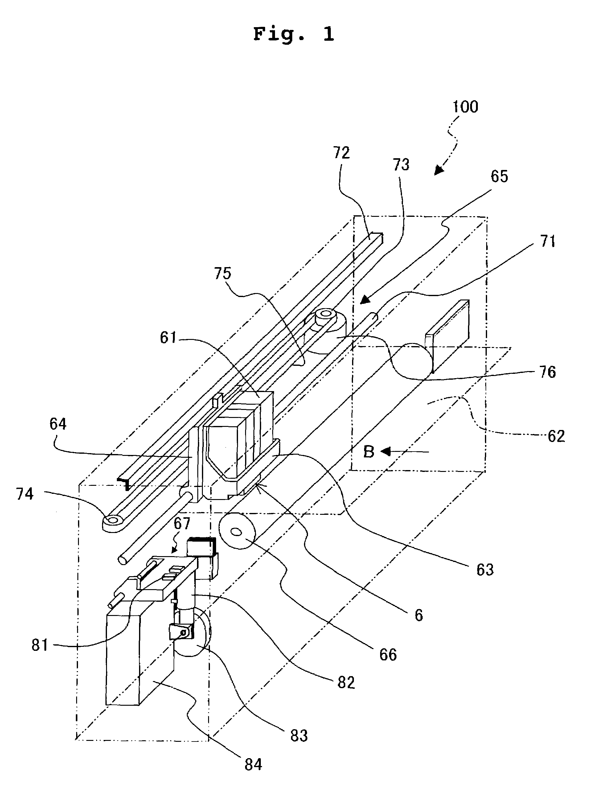
[0061]An explanation will be made below on the basis of the accompanying drawings about an embodiment in which the droplet-jetting device of the present invention is applied to an ink-jet head. FIG. 1 shows a perspective view illustrating a schematic structure of a color ink-jet printer which carries the ink-jet head of the present invention. As shown in FIG. 1, the ink-jet printer 100 comprises ink cartridges 61 which are filled with four color inks of, for example, cyan, magenta, yellow, and black, a head unit 63 which is provided with piezoelectric ink-jet heads 6 for performing the printing on printing paper 62 to be fed in the direction of the arrow B in FIG. 1, a carriage 64 on which the ink cartridges 61 and the head unit 63 are carried, a drive unit 65 which allows the carriage 64 to make reciprocating movement in a direction perpendicular to the feeding direction of the printing paper 62, a platen roller 66 which extends in the direction of the reciprocating movement of the...

second embodiment

[0096]Another embodiment of the droplet-jetting device according to the present invention will be explained with reference to FIGS. 12 to 27. The droplet-jetting device of this embodiment is constructed in the same manner as in the first embodiment except that the structure of the piezoelectric ink-jet head is changed.

[0097]At first, the structure of a piezoelectric ink-jet head 106 will be explained with reference to FIGS. 18 to 22. FIG. 18 shows an exploded perspective view illustrating the piezoelectric ink-jet head 106. FIG. 19 shows a side sectional view illustrating the piezoelectric ink-jet head 106. FIG. 20 shows an exploded perspective view illustrating a cavity plate 110. FIG. 21 shows an exploded perspective view illustrating magnified main components of the cavity plate 110. FIG. 22 shows an exploded perspective view illustrating magnified main components of a piezoelectric actuator 120.

[0098]As shown in FIGS. 18 and 19, the piezoelectric ink-jet head 106 is constructed ...


PUM


Abstract

A droplet-jetting device, which is usable for an ink-jet recording apparatus, comprises a pressure chamber disposed between a cavity plate and a pressure-generating section of a piezoelectric actuator. The pressure-generating section and the cavity plate are connected by a connecting section. When a voltage is applied to the piezoelectric actuator, the pressure-generating section is elongated to depress the bottom of the pressure chamber downwardly so that the volume of the pressure chamber is increased. The droplet-jetting device is realized, in which the area of arrangement of the pressure-generating section is decreased to suppress the electrostatic capacity and the pull-eject can be performed by applying the voltage only when the device is driven.

Description

BACKGROUND OF THE INVENTION[0001]1. Field of the Invention[0002]The present invention relates to a droplet-jetting device such as an ink-jet head of an ink-jet printer.[0003]2. Description of the Related Art[0004]An apparatus has been hitherto suggested, in which a piezoelectric droplet-jetting device is utilized for a print head. This device is constructed such that the volume of a liquid chamber is changed by the dimensional displacement of a piezoelectric actuator, and thus the liquid (ink) contained in the liquid chamber is jetted from a nozzle during the decrease of the volume, while the ink is introduced into the liquid chamber during the increase of the volume. A large number of the droplet-jetting devices as described above are arranged closely to one another, and the ink is jetted from the droplet-jetting device disposed at a predetermined position. Accordingly, a desired letter or an image is formed.[0005]For example, FIG. 28 shows an ink-jet print head which utilizes the ...

Claims


Application Information

Patent Timeline
IPC IPC(8): B41J2/045B41J2/04B41J2/14
CPCB41J2/14209B41J2/14233B41J2/14274B41J2002/14225B41J2002/14258
Inventor TAKAHASHI, YOSHIKAZUISHIKAWA, HIROYUKI
Owner BROTHER KOGYO KK
Why Eureka
Try Eureka