Turbine nozzle trailing edge cooling configuration

a technology of turbine nozzles and cooling configurations, which is applied in the direction of machines/engines, stators, liquid fuel engines, etc., can solve the problems of high degree of bowing and twisting of three-dimensional advanced airfoil nozzle vanes, insufficient space, and the need for additional trailing edge circuits, etc., to achieve the effect of high degree of bowing and twisting and higher external heat load

Active Publication Date: 2006-10-17
GENERAL ELECTRIC CO
View PDF3 Cites 41 Cited by
  • Summary
  • Abstract
  • Description
  • Claims
  • Application Information

AI Technical Summary

Problems solved by technology

The additional trailing edge circuit is required due to geometric limitations of the vane, i.e., there is insufficient space within the airfoil cavity to extend the aft impingement insert to the trailing edge.
Furthermore, three-dimensional advanced airfoil nozzle vanes have a high degree of bowing and twist.
This lengthens the trailing edge region where impingement cooling using inserts is not mechanically practical.
Pin cooling, however, is associated with a substantial pressure drop and is practical over very short distances.
However, those designs often achieve insufficient cooling efficiency to meet cooling performance requirements for the nozzle vane.

Method used


Image

  • Turbine nozzle trailing edge cooling configuration
  • Turbine nozzle trailing edge cooling configuration
  • Turbine nozzle trailing edge cooling configuration

Examples


Embodiment Construction

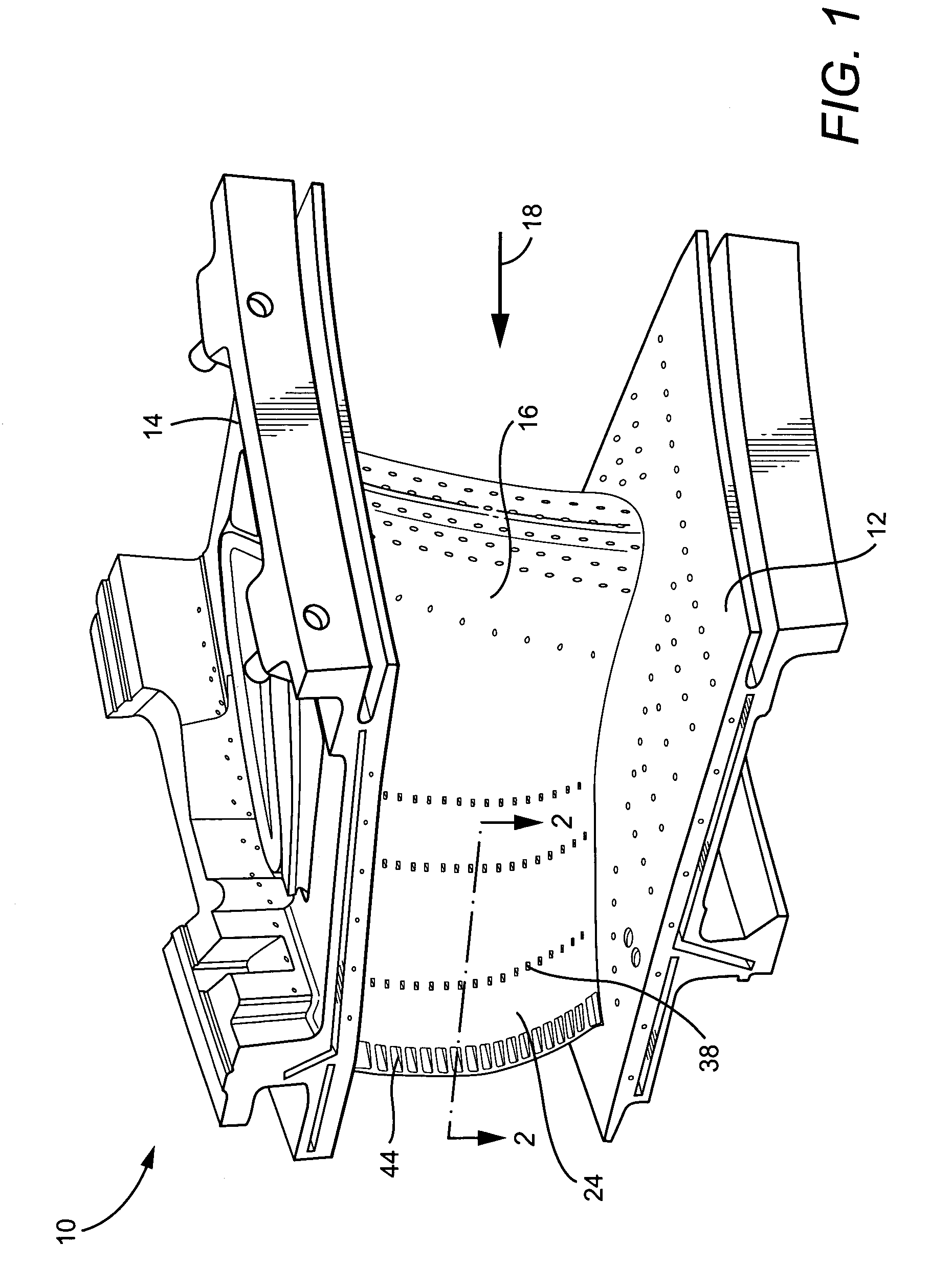
[0010]Referring now to the drawings, particularly to FIG. 1, there is illustrated a nozzle segment generally designated 10 including an inner platform 12, an outer platform 14 and an airfoil or vane 16 extending between the inner and outer platforms. It will be appreciated that the nozzle segment 10 is one of a plurality of nozzle segments which are arranged in a circumferential array thereof about a turbine axis and which form a fixed or stationary part of a stage of a turbine, for example, the first stage of a turbine. Also, while a single airfoil or vane 16 is illustrated between the inner and outer platforms 12 and 14, respectively, each segment may contain two or more airfoils or vanes extending between the platforms. In the illustrated segment, the cooling holes are provided in various parts of the inner and outer platforms as well as the airfoil to cool the various parts of the nozzle segment, it being further appreciated that the inner and outer platforms and the airfoil or ...


PUM


Abstract

The trailing edge region of a nozzle airfoil is provided with a cooling configuration wherein post-impingement cooling air flows between radially spaced ribs defining convective cooling channels into a generally radially extending plenum. Cooling air in the plenum is split between film cooling holes for film cooling the pressure side of the trailing edge region and for flow about downstream pins for pin cooling the downstream regions of the opposite sides of the airfoil. The cooling air exiting the pins is directed through convective channels defined by a second set of radially spaced ribs and through exit apertures on the pressure side of the trailing edge.

Description

BACKGROUND OF THE INVENTION[0001]The present invention relates to a trailing edge air cooling configuration for a turbine nozzle, and particularly relates to a hybrid convective channel and pin cooling configuration for the trailing edge portion of a gas turbine nozzle vane.[0002]Gas turbine nozzle cooling is typically achieved by locating impingement inserts within the airfoil cavities, e.g., two or more cavities of the first stage nozzle of a gas turbine. The pressure and suction sides of the vane are thus impingement cooled. The post-impingement cooling air is then either discharged through film holes along the airfoil surface to provide an insulating barrier of cooler air between the hot gas stream and the airfoil or sent to an additional circuit to convectively cool the airfoil trailing edge. The additional trailing edge circuit is required due to geometric limitations of the vane, i.e., there is insufficient space within the airfoil cavity to extend the aft impingement insert ...

Claims


Application Information

Patent Timeline
Patent Type & Authority Patents(United States)
IPC IPC(8): F01D9/02F01D5/18F01D5/14
CPCF01D5/186F01D5/187F05D2260/201F05D2260/2212F05D2260/22141F05D2240/81
Inventor JACKS, CURTIS JOHNCOIGN, ROBERT WALTERGILL, RANDALL DOUGLAS
Owner GENERAL ELECTRIC CO
Why Eureka
Try Eureka