
Terminal block equipped with a cover

a terminal block and cover technology, applied in the direction of coupling bases/cases, substation/switching arrangement boards/panels/desks, coupling device connections, etc., can solve the problems of short circuit between the terminals, signal wire disconnecting still possible, signal wire disconnecting, etc., to facilitate wiring and repair and maintenance

Inactive Publication Date: 2006-10-17
SURTEC INDS
View PDF10 Cites 12 Cited by
  • Summary
  • Abstract
  • Description
  • Claims
  • Application Information

AI Technical Summary

Benefits of technology

[0007]In view of the aforesaid problems, the primary object of the present invention is to provide a terminal block equipped with a cover. The cover can be automatically aligned and hinged on the terminal block to shield and protect the terminals and signal wires on the terminal block. The cover also may be removed quickly to facilitate wiring and repairs and maintenance.
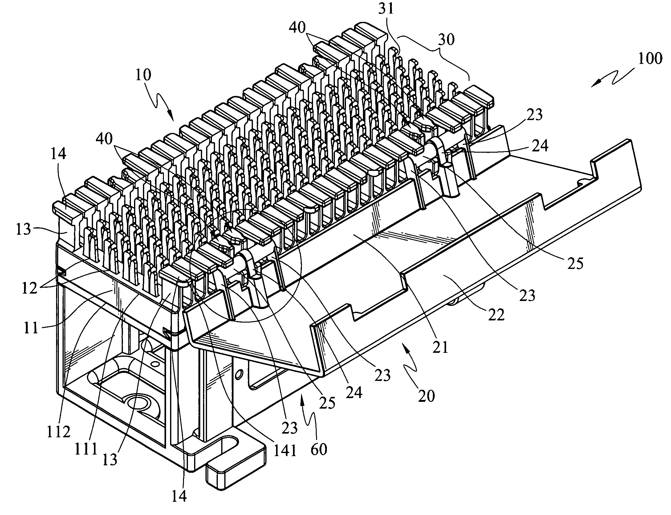
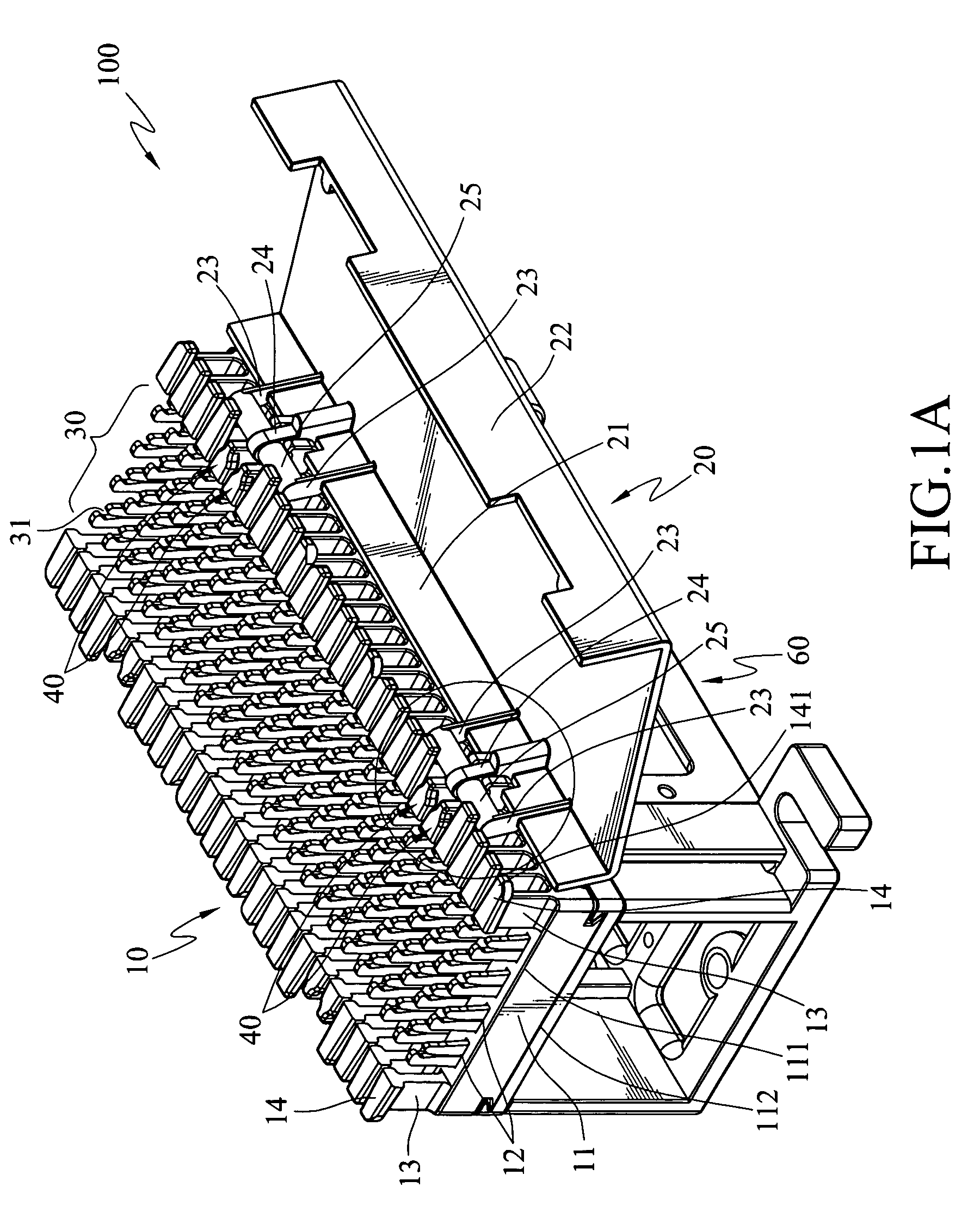
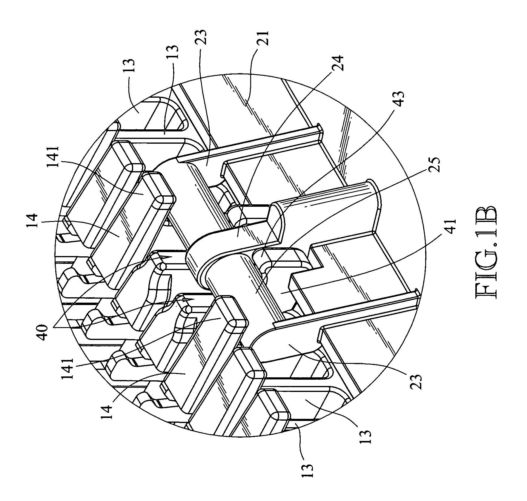
[0008]To achieve the foregoing object, the terminal block equipped with a cover according to the invention includes a terminal block, pivot plates and a cover. The terminal block has a plurality of terminals to connect signal wires on the top surface and a plurality of guiding plates on two sides. Each guiding plate has a top plate on the top end. The top plate has a flange extending outwards on a outer edge. There are two sets of pivot plates, and each set includes a pair of pivot plates. Each set of pivot plates is located on one side of the terminal block, and each one of the pivot plates is located between two guiding plates. Furthermore each pivot plate has a holding portion extended outwards from the terminal block. The holding portion has a coupling trough, which has an opening with a detent portion located thereon. The cover further has a plurality of axles on one side corresponding to each set of the pivot plates. The axle is wedged in the coupling trough. The flange of the top plate and the detent portion of the pivot plate can confine the axle so that the axle is held securely in the coupling trough without escaping and can rotate in the coupling trough. Therefore the cover can be swiveled relative to the terminal block and shield the terminal block to protect the terminals from being hit by external articles. Thus short circuit or disconnecting of the signal wires can be prevented.
[0009]As the relative position of the cover and the terminal block is aligned by coupling of the axle and the coupling trough, and the cover can be automatically hinged on one side of the terminal block on a correct position to cover the terminal block accurately. In addition, because the cover and the terminal block can be positioned accurately, labeling may be made on the corresponding positions of the cover to classify the terminals according to connecting conditions. Hence wiring operation is simpler and the signal wires of different connection may be identified easily.
[0010]The present invention can provide many advantages. For instance, as the pivot plate is a portion of the terminal block, it can be integrally formed on the terminal block to reduce the number of elements. Compared with U.S. Pat. No. 4,697,720, the present invention does not need to add extra hinge elements to hinge the cover on one side of the terminal block. Moreover, after the axle of the cover is wedged in the coupling trough, the cover and the terminal block are positioned on correct positions so that the cover can completely shield all terminals and provide desired protection. Exposure of terminals may be prevented. As the cover can be positioned on the correct location, labeling may be made on the cover to facilitate identification and classification of the terminals and signal wires.

Problems solved by technology

As the terminals are exposed on the top surface of the terminal block, they are easily hit by external articles and result in a shot circuit between the terminals, or result in disconnecting of the signal wires.
A slight deviation could expose the terminals and result in being hit by external articles.
As a result, a short circuit between the terminals or disconnecting of the signal wires still could happen.

Method used


Image

  • Terminal block equipped with a cover
  • Terminal block equipped with a cover
  • Terminal block equipped with a cover

Examples


Embodiment Construction

[0017]Refer to FIGS. 1A, 1B and 2 for an embodiment of the present invention. The connecting device 100 includes a terminal block 10 and a cover 20, which covers the upper side of the terminal block 10 to provide shielding and protection.

[0018]The terminal block 10 is a commonly used element in telecommunication. It is made from insulation materials, such as plastics. The terminal block 10 includes a body 11, which has a top surface 111 and a bottom surface 112. The top surface 111 has a plurality of insertion holes 12 to receive a plurality of terminals 30. The insertion holes 12 may be arranged in different layouts according to requirements. In this embodiment, the insertion holes 12 are laid in a plurality of rows in a spaced manner. Hence the terminals 30 also are arranged in a spaced manner on the body 11. Each terminal 30 has a slot 31 in the longer axial direction to clip a signal wire (not shown in the drawings) to form an electric connection between the signal wire and the ...


PUM

PropertyMeasurementUnit
widthaaaaaaaaaa
shapeaaaaaaaaaa
flexibleaaaaaaaaaa

Abstract

A terminal block equipped with a cover includes a cover and a terminal block. The terminal block has pivot plates on two sides. Each pivot plate has a coupling trough. The cover has an axle on one side, to be wedged in the coupling trough, so that the cover may be hinged on one side of the terminal block. The cover may be turned to shield the terminal block. Wedging of the axle in the coupling trough also forms an anchoring effect to position the cover on a correct location relative to the terminal block, so that the cover can fully shield the terminal block, to provide desired covering and protection.

Description

BACKGROUND OF THE INVENTION[0001]1. Field of Invention[0002]The present invention relates to conductors for communication equipment. More particularly, The present invention relates to a terminal block equipped with a cover that includes a cover hinged on one side of the terminal block and anchored on a correct location to completely cover the terminal block.[0003]2. Related Art[0004]The terminal block is widely used in telecommunication systems to connect signal wires on one location to facilitate maintenance and management. U.S. Pat. No. 3,887,259 discloses such a connecting device, which has a rectangular terminal block made from an insulation material. The terminal block has a plurality of guiding plates on two longer sides that are spaced from one another to allow the signal wires to pass through. The signal wires may be divided according to different signal sources and classified according to their functions. The terminal block further has a plurality of terminals. Each termin...

Claims


Application Information

Patent Timeline
Patent Type & Authority Patents(United States)
IPC IPC(8): H01R9/22H01B17/00H01R13/447H01R13/50H02B1/06
CPCH01R9/223H01R13/447H01R13/501
Inventor CHEN, MICHAEL
Owner SURTEC INDS
Learn More