Surfcraft removable fin system improved plug installation

a technology of fins and plugs, which is applied in the direction of special-purpose vessels, vessel construction, hull parts, etc., can solve the problems of large perimeter or edge between the anchor and the resin coating, inability to fit fins into the plugs, and special spacing tools and extra labor

Inactive Publication Date: 2006-10-17
HICKMAN SCOTT NOBLE
View PDF11 Cites 21 Cited by
  • Summary
  • Abstract
  • Description
  • Claims
  • Application Information

AI Technical Summary

Problems solved by technology

If the spacing is not correct the fin will not fit into the plugs.
This creates a problem requiring a special spacing tool and extra labor during manufacturing.
Also, the large perimeter, o

Method used


Image

  • Surfcraft removable fin system improved plug installation
  • Surfcraft removable fin system improved plug installation
  • Surfcraft removable fin system improved plug installation

Examples


Embodiment Construction

Description—FIGS. 1–5—Preferred Embodiment

[0035]A preferred embodiment my fin system is illustrated in FIGS. 1 through 5.

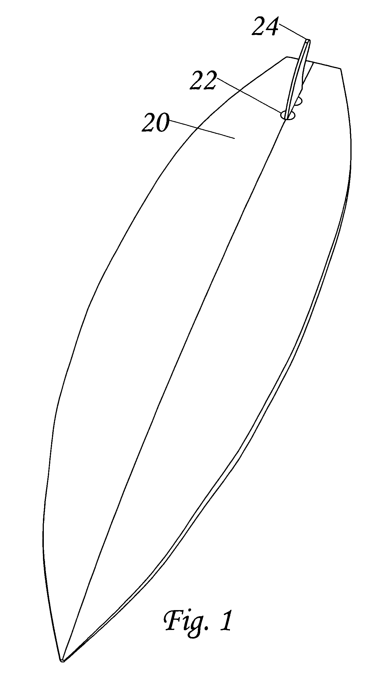
[0036]FIG. 1 is an overall view of a fin 24 in a surfcraft 20 anchored with two separate plugs 22. The surfcraft has been sanded and is in the condition that a user will employ.

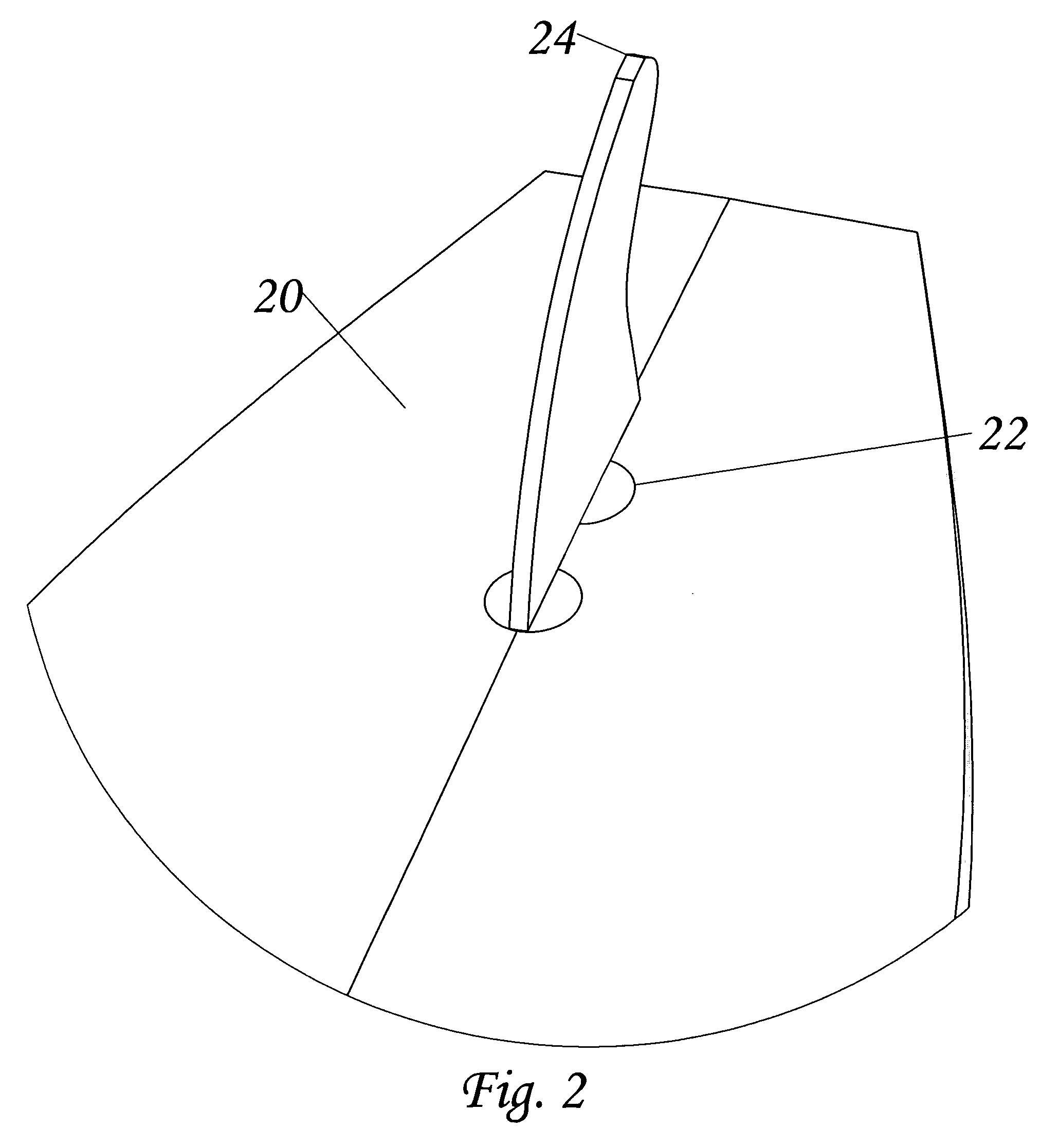
[0037]FIG. 2 is a detail view of FIG. 1. The surfcraft 20 has been sanded. It is in the condition that a user will employ.

[0038]FIG. 3 is a section view of the fin system of FIG. 2 showing the surfcraft 20. Plugs 22 are shown adhered with resin 32. A fin 24 is installed in the plugs. Fin tabs 28 are inserted into plug recesses 26. The surfcraft has been sanded and is in the condition that a user will employ.

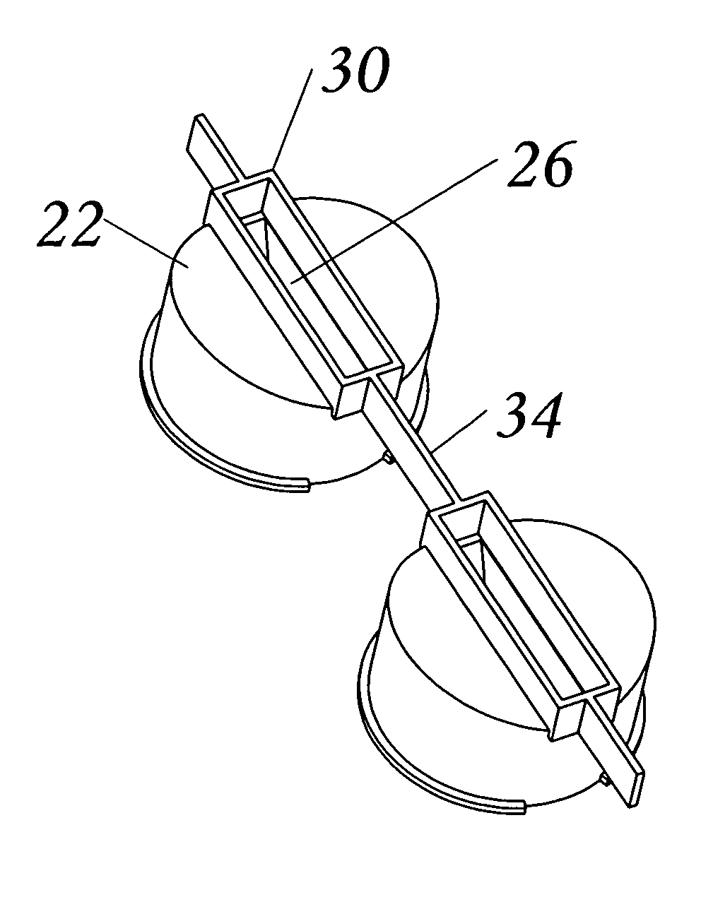
[0039]FIG. 4 is the same section view as FIG. 3. The fin is not shown and the plugs 22 have not been sanded. The skirt 30 has not been sanded away. The plugs are connected by a rib 34. The plugs have recesses 26. The plugs are adhered to the surfcraft by resin 32.

[0040]FIG. 5 is an isome...


PUM


Abstract

A surfcraft fin system utilizing a rib between fin anchors. The rib sets the distance between the anchors eliminating the need for a manufacturing jig. The rib is removed during the surfcraft manufacturing process resulting in multiple fin anchors adhered into the surfcraft.

Description

CROSS REFERENCES TO RELATED APPICATIONS[0001]Not applicable.FEDERALLY SPONSORED RESEARCH[0002]Not applicable.SEQUENCE LISTING OR PROGRAM[0003]Not applicable.BACKGROUND[0004]1. Field of Invention[0005]Surfing and surfcraft have always been very popular. Recently, traveling for surf has become increasingly popular. Travel to exotic locations with surfing gear creates new problems for surf equipment designers. Surfcraft fins are now commonly made removable to solve some of these problems. Surfcraft without removable fins are often damaged during airplane baggage handling. Because the fins protrude awkwardly from the surfcraft, they can be bumped and stressed beyond their strength resulting in damage.[0006]Several systems exist for fastening and removing fins to and from surfcraft. During the manufacture of the surfcraft each of these systems requires routing or drilling with a hole saw. Most fin systems use a box to anchor the fin into the surfcraft. A box requires routing for installa...

Claims


Application Information

Patent Timeline
IPC IPC(8): B63B1/00
CPCB63B35/793B63B32/66
Inventor HICKMAN, SCOTT NOBLE
Owner HICKMAN SCOTT NOBLE
Why Eureka
Try Eureka